Transmission arrangement
a technology of transmission arrangement and transmission device, which is applied in the direction of control device, coupling-brake combination, vehicle components, etc., can solve the problem that the axial force exerted on the brake device cannot be transmitted by the freewheel devi
- Summary
- Abstract
- Description
- Claims
- Application Information
AI Technical Summary
Benefits of technology
Problems solved by technology
Method used
Image
Examples
Embodiment Construction
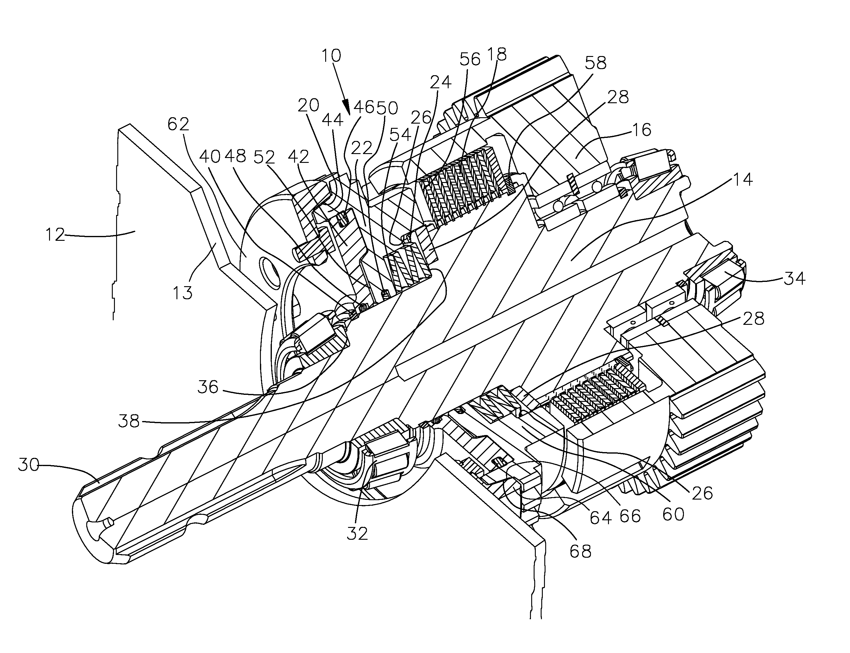
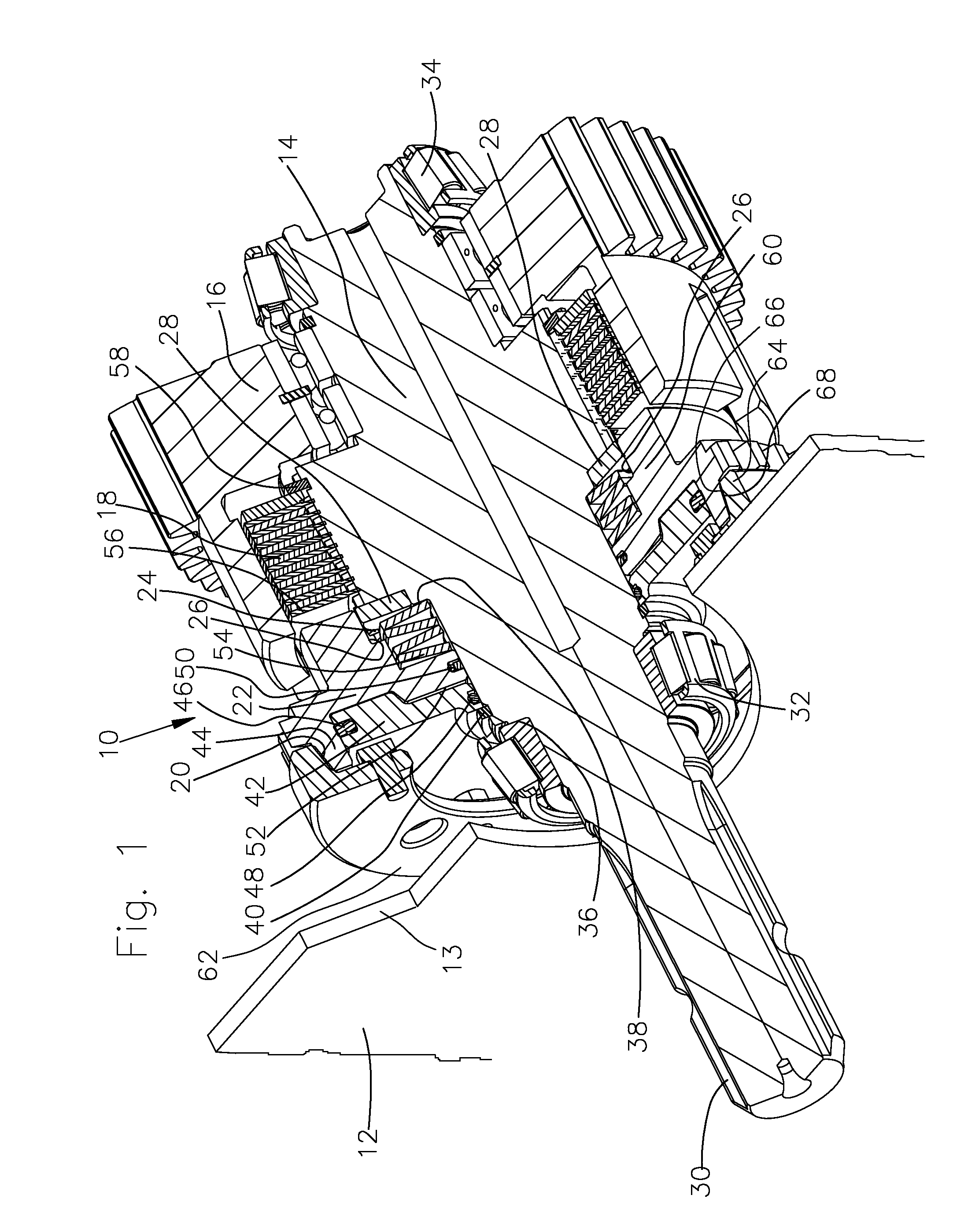
A transmission arrangement 10 is represented in FIG. 1 for a power take-off transmission of an agricultural tractor, for example, comprises a transmission housing 12 with a transmission housing wall 13, an output shaft 14 embodied as a power take-off shaft, a drive component 16 embodied as a gear shaft, a clutch 18 arranged between the output shaft 14 and the drive component 16, a brake device 20 and an annular piston 22 arranged between the clutch 18 and the brake device 20.
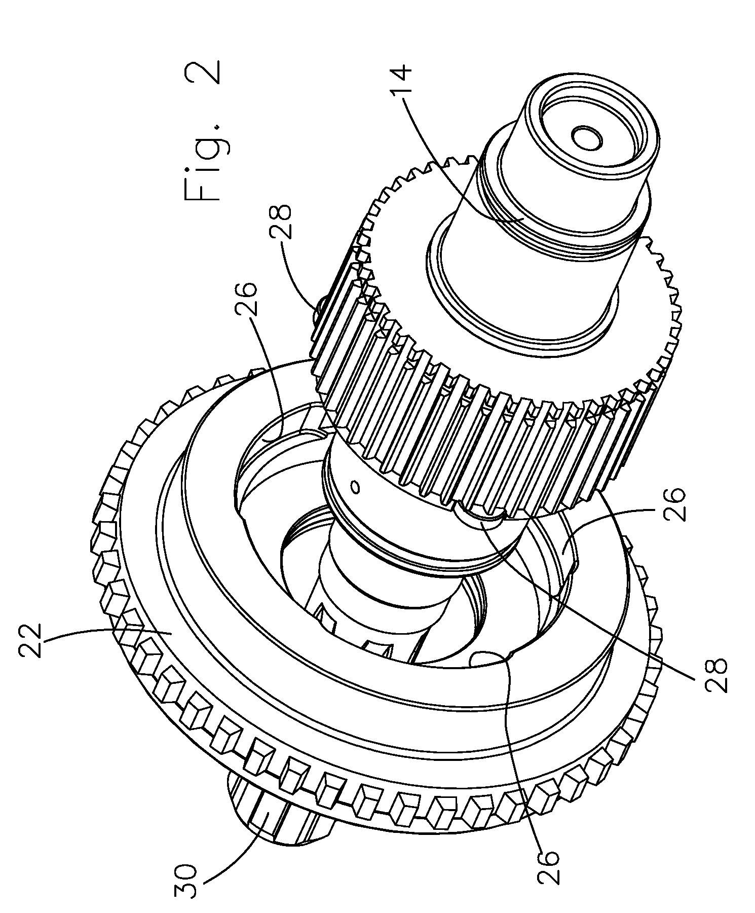
The annular piston is supported so that it is axially displaceable on the output shaft and is rotationally connected to the output shaft 14 by a freewheel device 24. The annular piston 22 therefore serves as torque transmission between the output shaft 14 and the drive element 16 and between the output shaft 14 and the brake device 20, as will be explained in more detail later.
The freewheel device 24 is formed by a recesses 26 formed on the annular piston 22 and by freewheel elements 28 fixed to the output shaft...
PUM
 Abstract
Description
Claims
Application Information
 - R&D
- Intellectual Property
- Life Sciences
- Materials
- Tech Scout
- Unparalleled Data Quality
- Higher Quality Content
- 60% Fewer Hallucinations
Browse by: Latest US Patents, China's latest patents, Technical Efficacy Thesaurus, Application Domain, Technology Topic, Popular Technical Reports.
© 2025 PatSnap. All rights reserved.Legal|Privacy policy|Modern Slavery Act Transparency Statement|Sitemap|About US| Contact US: help@patsnap.com


