Wipes dispenser

a dispenser and wipe technology, applied in liquid dispensing, special dispensing means, rigid containers, etc., can solve the problems of not being able to directly spray a hard surface with the sprayer, and each of these systems is deficient in some respects

Active Publication Date: 2011-08-30
SC JOHNSON & SON INC
View PDF16 Cites 24 Cited by
  • Summary
  • Abstract
  • Description
  • Claims
  • Application Information

AI Technical Summary

Benefits of technology

[0009]The container has an outlet and an internal area suitable to retain a liquid. When a spray bottle is used the outlet is preferably in a spray head that extends externally of the housing, such that if a liquid is stored in the spray bottle and a consumer moves the spray head it can cause the liquid to be delivered from the bottle and sprayed out the outlet. The spray head, and thus the outlet, can preferably pivot on an essentially vertically axis to provide additional flexibility in directing the spray. The bottle may also be linked to a pump sprayer.
[0011]The supply of wipe material is preferably in the form of a roll, and the wipes are positioned within the cavity such that a portion of the wipe material is capable of being moved (e.g. dragged) in front of the outlet. A second door can be pivotably mounted on the housing and act to cover the stored wipe material and the first door. The second door may also contain a hole to facilitate manual movement of the wipe material.
[0015]Note that the dispenser is compact, portable, and can be constructed from inexpensive plastics (apart from the cleaning liquid).

Problems solved by technology

However, pre-impregnating the wipe with the liquid requires the dispensing container to have structures which prevent the wipes from drying out prior to use.
Each of these systems is deficient in some respect.
For example, it is typical for the sprayer not to be usable to spray a hard surface directly, or not be well positioned to impregnate the wipe.

Method used


Image

  • Wipes dispenser
  • Wipes dispenser
  • Wipes dispenser

Examples


Embodiment Construction

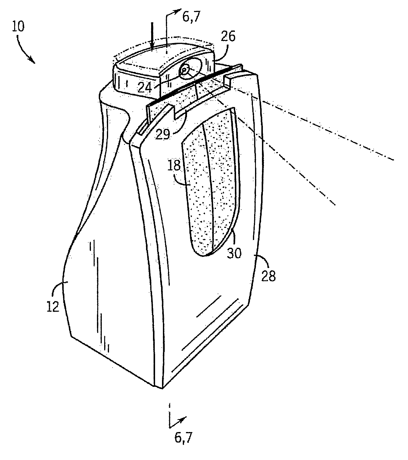
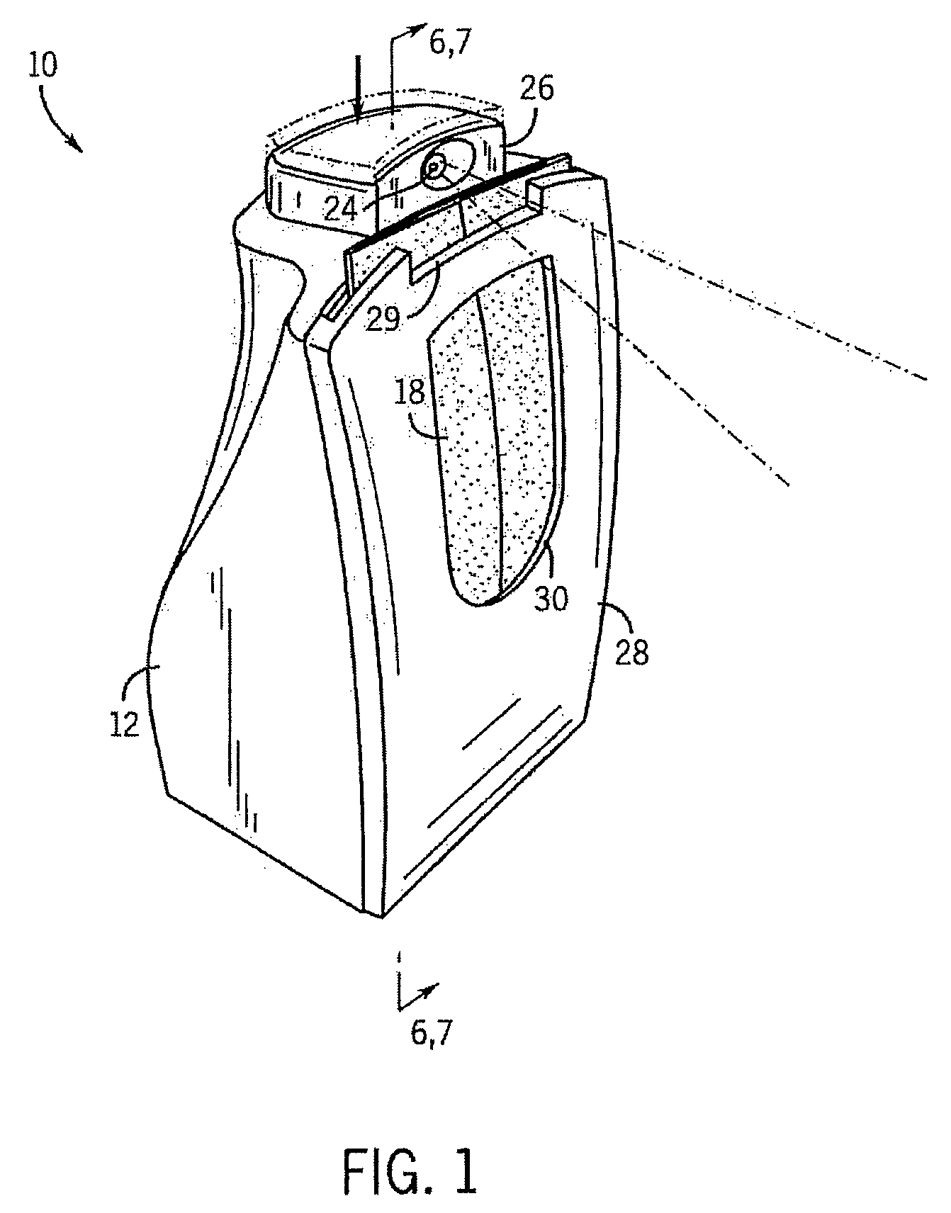
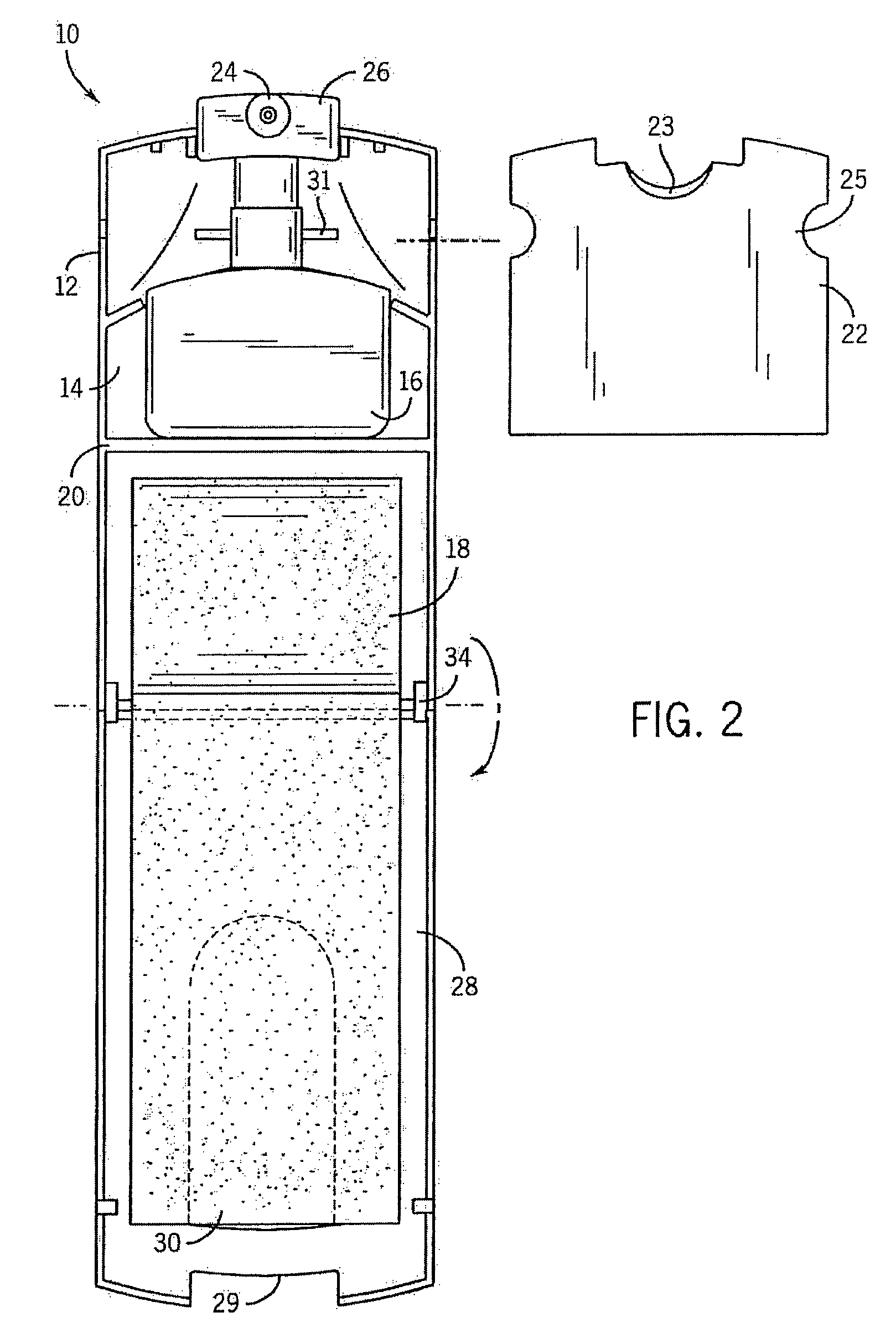
[0027]The drawings depict a wipes dispenser 10 having a housing 12 having an internal cavity 14, a container in the form of a spray bottle 16 positioned in the cavity 14, and a supply (e.g. a stack or roll) of wipe 18 also positioned in the cavity 14.

[0028]The spray bottle 16 is mounted on a ledge 20 that is positioned above the supply of wipe 18. The bottle 16 has an outlet 24 and an internal area suitable to retain a liquid (not shown).

[0029]The outlet 24 is positioned in a spray head 26 that extends externally of the housing 12, and is linked to a conventional pumping assembly. If a liquid is stored in the spray bottle 16 and a consumer depresses the spray head 26 it can cause the liquid to be delivered from the bottle 16 and sprayed out the outlet 24.

[0030]A first door 22 retains the spray bottle 16 in the cavity 14. The first door 22 contains opposing c-shaped openings 25 configured to releasably engage the housing 12 around the spray bottle 16. The first door 22 also contains ...


PUM

PropertyMeasurementUnit
areaaaaaaaaaaa
structuresaaaaaaaaaa
flexibilityaaaaaaaaaa

Abstract

Portable wipe dispensers are provided. In one form the wipe dispenser can be used to spray a cleaning liquid onto a wipe being dispensed from the device. Alternatively the outlet may be directed against a surface external to the dispenser.

Description

CROSS-REFERENCE TO RELATED APPLICATIONS[0001]This application claims priority based on U.S. provisional application 60 / 970,093 filed on Sep. 5, 2007.STATEMENT REGARDING FEDERALLY SPONSORED RESEARCH / DEVELOPMENT[0002]Not applicable.BACKGROUND OF THE INVENTION[0003]The present invention relates generally to wipe dispensing systems. More particularly, the present invention relates to wipe dispensing systems that allow a consumer to selectively apply a cleaning chemical to the wipe, or alternatively to a surface external to the dispenser and / or alternatively dispense dry wipes.[0004]Wipes may be treated with detergent, other hard surface cleaners, polishes, waxes and other liquid materials. For example, so called “baby wipes” are treated with a mild cleaning agent or other substance for cleaning a baby's skin. Such wipes are generally packaged into a container like that of U.S. Pat. No. 5,803,249 from which the wipes can be dispensed.[0005]However, pre-impregnating the wipe with the liqu...

Claims


Application Information

Patent Timeline
Patent Type & Authority Patents(United States)
IPC IPC(8): A47F1/00B65H3/00B67D7/06B67D1/07G07F11/00B67D7/58
CPCA47K10/32B65D83/0847B05B11/30A47K2010/328B05B11/10
Inventor FRYAN, MICHAEL C.SOLLER, DOUGLAS A.POPLI, RAKESH K.STEER, FRANK J.SPARKS, EVAN A.
Owner SC JOHNSON & SON INC
Why Eureka
Try Eureka