Sealed flange joint for high pressure and high purity gas channels

a flange joint and high purity technology, applied in the direction of couplings, pipes, branching pipes, etc., to achieve the effect of facilitating the assembly of flange joints

Inactive Publication Date: 2011-08-30
LUXEMBOURG PATENT CO SA
View PDF18 Cites 5 Cited by
  • Summary
  • Abstract
  • Description
  • Claims
  • Application Information

AI Technical Summary

Benefits of technology

[0009]The present invention thus proposes a joint design where the nipple, pressing against the interior side of the polymer seal ring, causes a strong radial compression of the latter. This is due to the configuration of nipple and polymer seal ring when both flanges are assembled and secured together. The nipple with its conical head transforms the axial pressures into radial compression of the polymer seal ring. The seal ring is thus radially compressed and in fact confined between the nipple and surfaces of the front cavity, which provides a high quality seal that is adapted for high operating pressures, as is often the case in high-purity gas applications.
[0021]In some embodiments, the height of the nipple may be such that a small gap separates the end surface of the conical head of the nipple from the ground surface of the front cavity when the first and second abutment surfaces have been axially pressed one against the other. In such case, the polymer seal ring is preferably designed such that, in the compressed state, it radially penetrates into this small gap to fill it up. This avoids any “dead volume” at the periphery of the fluid channels, where particles, condensation or gases / fluids could accumulate.

Problems solved by technology

Secondly, the use of a flange joint permits an axial assembly of the joint.

Method used


Image

  • Sealed flange joint for high pressure and high purity gas channels
  • Sealed flange joint for high pressure and high purity gas channels
  • Sealed flange joint for high pressure and high purity gas channels

Examples


Embodiment Construction

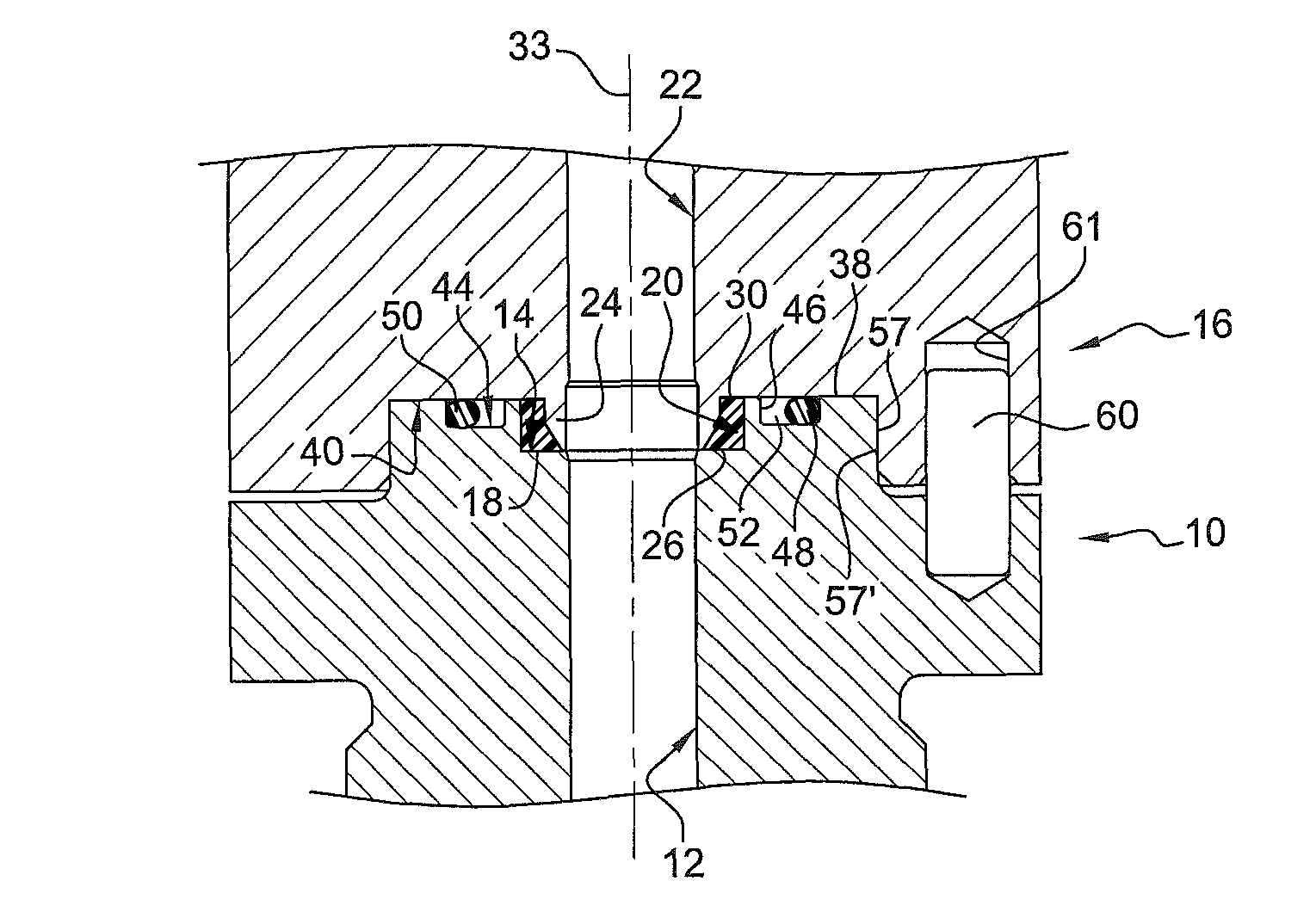
[0033]A preferred embodiment of a sealed flange joint in accordance with the present invention is illustrated in the Figures. The present sealed flange joint involves the assembly of a pair of flanges in a sealed manner, as will be seen below. Such flange joint design can be used for a variety of sealed connections in fluid, especially gas, channels and any fluid / gas containment, handling or dispensing systems, e.g. between a gas cylinder valve port and a delivery pipe. The present type of flange joint is particularly suited for applications using ultra pure, very corrosive and high pressure gases.

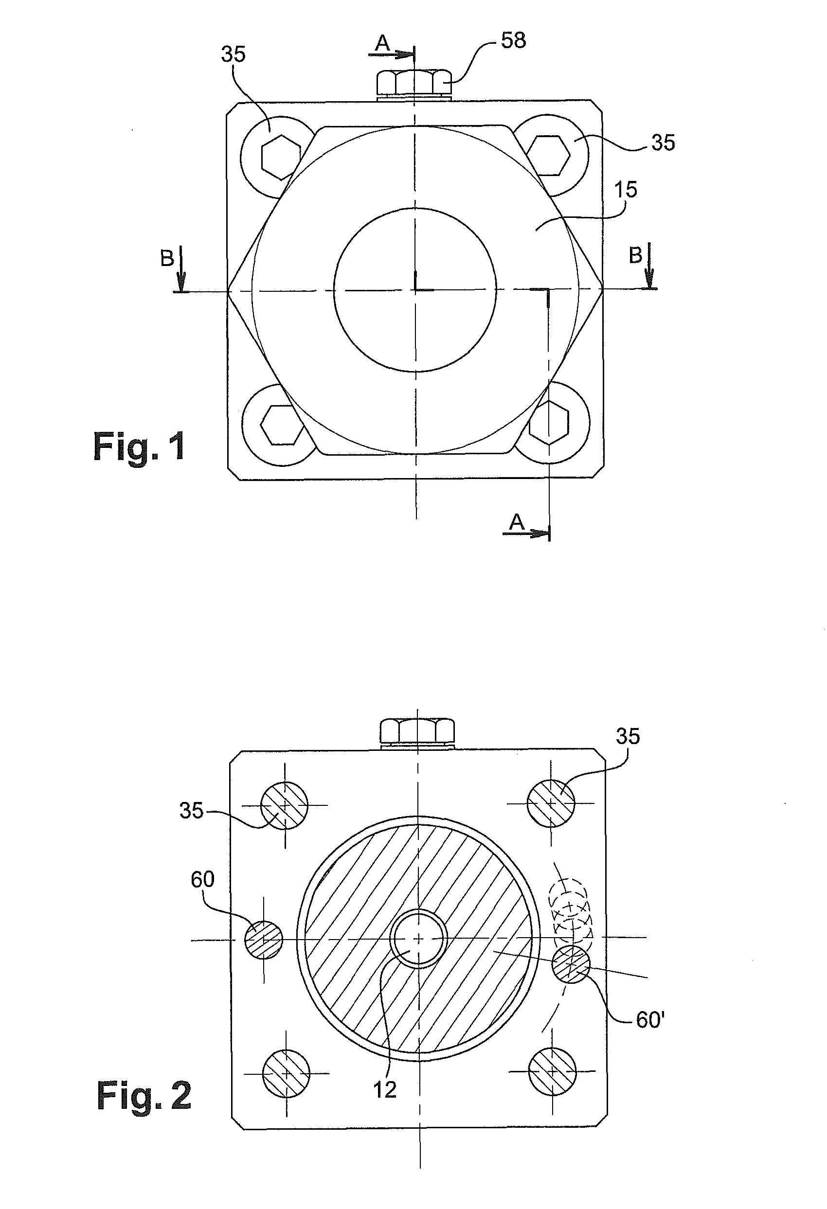
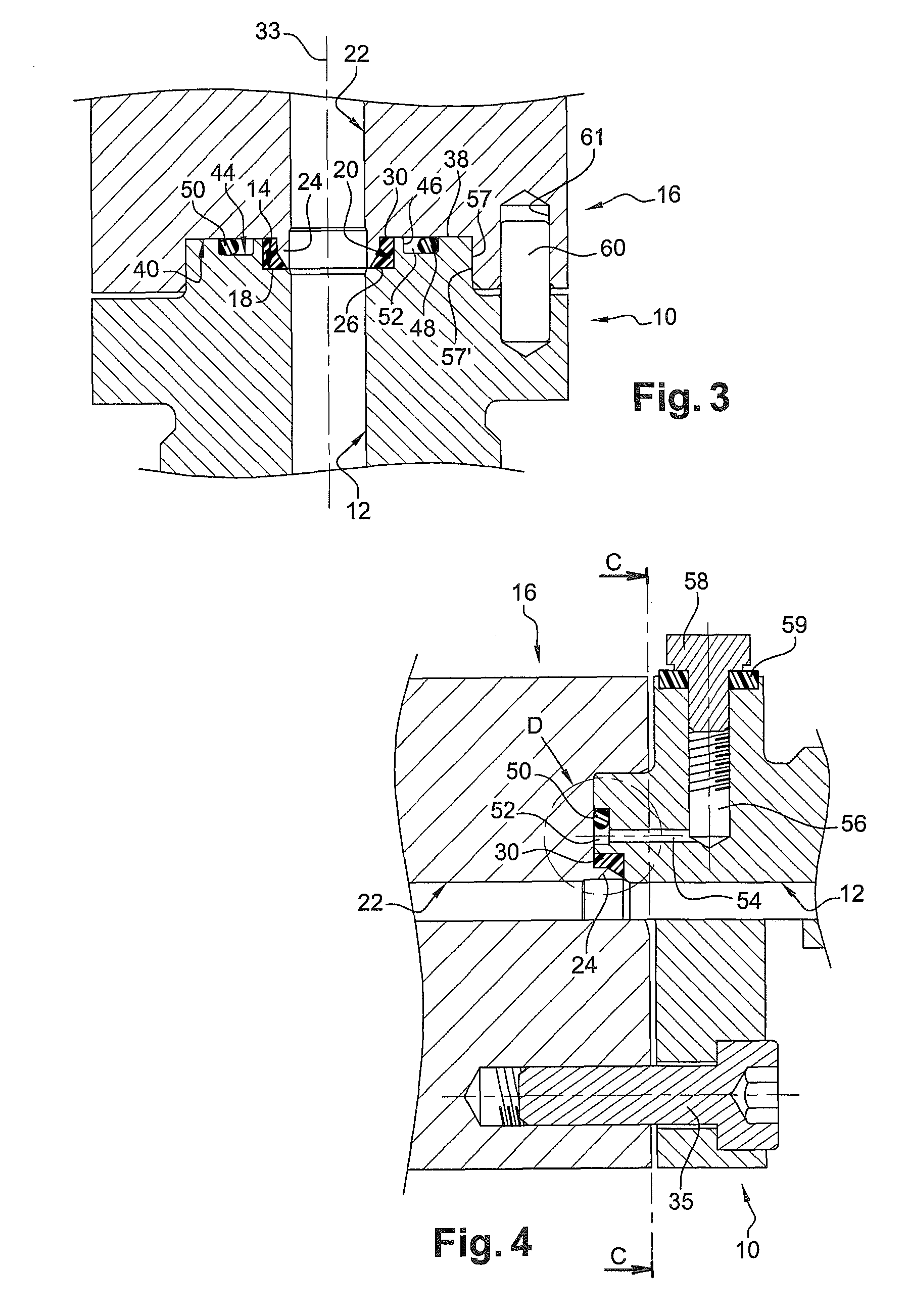
[0034]Turning now to FIG. 3, there is shown a first flange 10 having a first gas channel 12 and a cylindrical front cavity 14. This first flange 10 may e.g. be provided at the extremity of a delivery pipe 15. Reference sign 16 generally indicates a second flange, the two flanges 10 and 16 being removably fixed to one another, as will be explained further below. Such second flange structure...


PUM

PropertyMeasurementUnit
pressuresaaaaaaaaaa
operating temperaturesaaaaaaaaaa
shapeaaaaaaaaaa

Abstract

A sealed flange joint for high pressure and / or high purity fluid channels includes a first flange with a first fluid channel and a cylindrical front cavity. The front cavity is axially delimited by a ground surface and radially by a peripheral surface. The first fluid channel passes axially through the first flange to open into the ground surface. A polymer seal ring has a radial outer surface and a radial inner surface, and is fitted into the cylindrical front cavity so that its radial outer surface engages the peripheral surface of the front cavity. A second flange is removably fixed onto the first flange, and has a second fluid channel in axial continuation of the first fluid channel. The second flange has an axially protruding cylindrical front nipple with a conical head, the second fluid channel axially opening into an end surface of the conical head. The conical head engages the radial inner surface of the seal ring to radially press the latter with its radial outer surface against the peripheral surface of the front cavity.

Description

TECHNICAL FIELD OF THE INVENTION[0001]The invention generally relates to a sealed flange joint for fluid channels, in particular for high pressure and / or high purity gas channels.BRIEF DISCUSSION OF RELATED ART[0002]The expanded use of specialty gases, and the ever increasing levels of purity demanded by some of today's industries, has created a need for increasingly sophisticated delivery systems of the highest quality and integrity.[0003]In the semiconductor / chip manufacturing industry for example, high quality gas channels are required because any impurities in the gas can adversely affect the electrical properties of the devices and can greatly decrease the manufacturing yield. Most often these gases are also very reactive, corrosive and / or toxic.[0004]Hence, the containment, handling and delivery of ultra-pure gases requires specially adapted installations and high quality equipment. In such systems, the quality of the joints and sealing elements is of particular importance, to...

Claims


Application Information

Patent Timeline
Patent Type & Authority Patents(United States)
IPC IPC(8): F16L41/00
CPCF16L23/22F16L23/032F16L2201/30F16L47/14
Inventor MUZZO, PAULKREMER, PAUL
Owner LUXEMBOURG PATENT CO SA
Why Eureka
Try Eureka