Reaction cuvette wash unit

a technology of reaction cuvette and wash unit, which is applied in the field of wash unit, can solve the problems of damage to the cleaning needle and the reaction cuvette, damage to the cleaning nozzle, and high cost, and achieve the effect of simple structure, effective protection of the reaction cuvette from damage, and reliable operation

Inactive Publication Date: 2011-08-30
SHENZHEN MINDRAY BIO MEDICAL ELECTRONICS CO LTD
View PDF11 Cites 8 Cited by
  • Summary
  • Abstract
  • Description
  • Claims
  • Application Information

AI Technical Summary

Benefits of technology

[0004]The object of the present invention is to provide a driving device and an anticollision protective device for a reaction cuvette wash unit, and to provide a reaction cuvette wash unit comprising the driving device and the anticollision protective device, which equipment is capable of effectively protecting the reaction cuvette and cleaning needles.
[0013](1) The driving device has a simple structure, operates reliably and realizes a power-off self-locking.
[0014](2) The adoption of the elastic members provides an elastic contact while the cleaning needles touch the bottom surface of the reaction cuvette, such that a relatively small force is exerted upon the bottom of the reaction cuvette, thereby effectively protecting the reaction cuvette from damage.
[0015](3) The provision of the baffle plate and sensor makes it possible that when the wipe nozzle collides with the inwall of the reaction cuvette, the controller could stop the motor and in turn stop the cleaning needles from continuous access, such that the wipe nozzle, cleaning needles and the reaction cuvette are under effective protection.

Problems solved by technology

As there is no anticollision mechanism, the wipe nozzle may easily collide with the wall of the cuvette when it gets access into the reaction cuvette, thereby making the wipe nozzle, cleaning needles and the reaction cuvette damaged.
Moreover, the existing structures are rather complicated.
They either move unevenly, or fail to perform the power-off self-locking in the vertical direction, or are compromised by a high cost.

Method used


Image

  • Reaction cuvette wash unit
  • Reaction cuvette wash unit
  • Reaction cuvette wash unit

Examples


Embodiment Construction

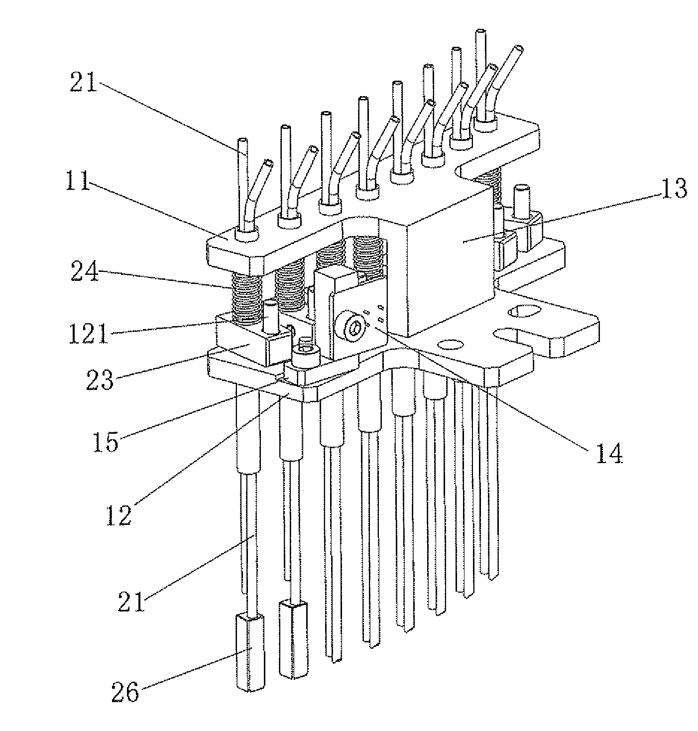
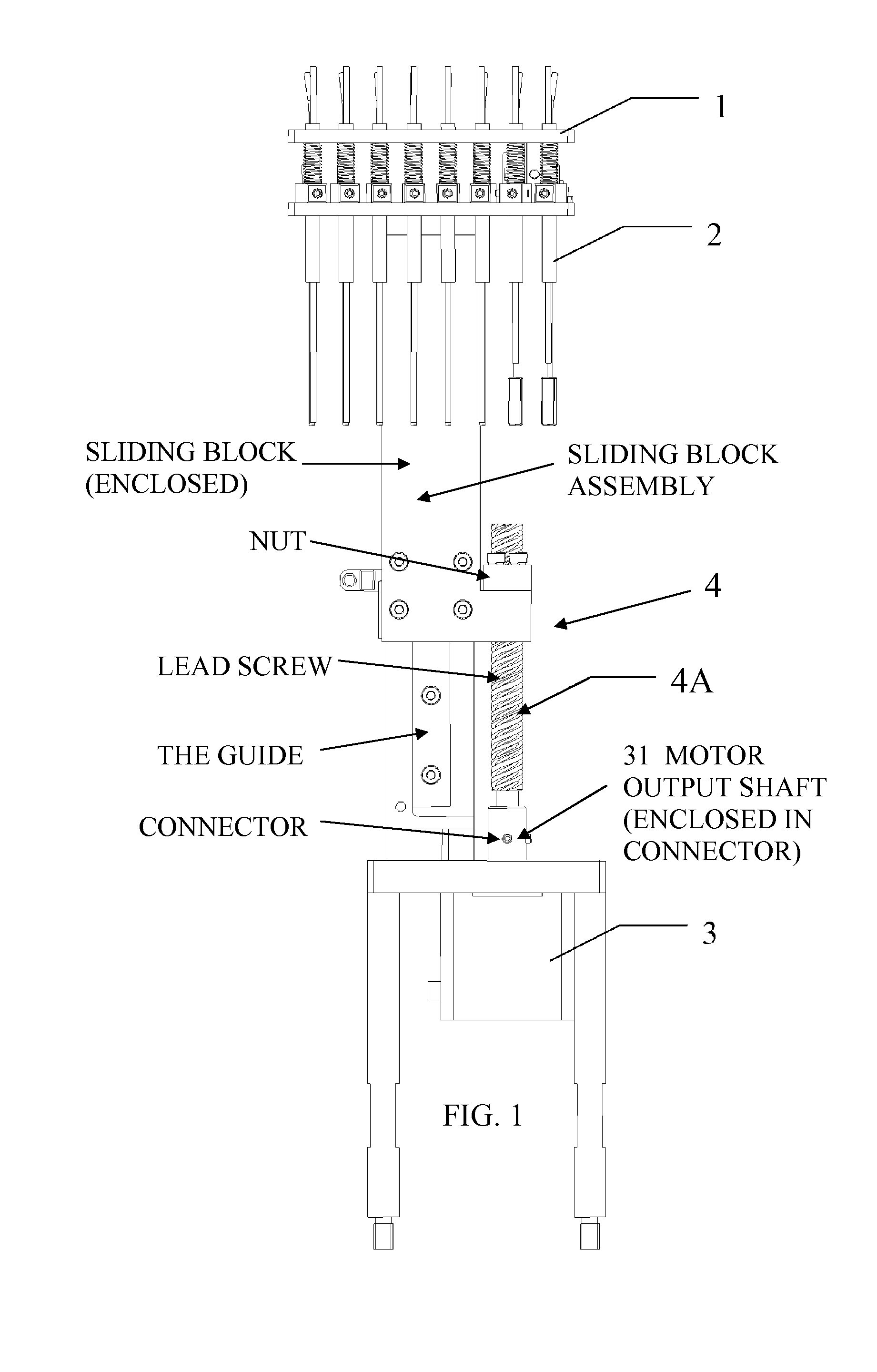
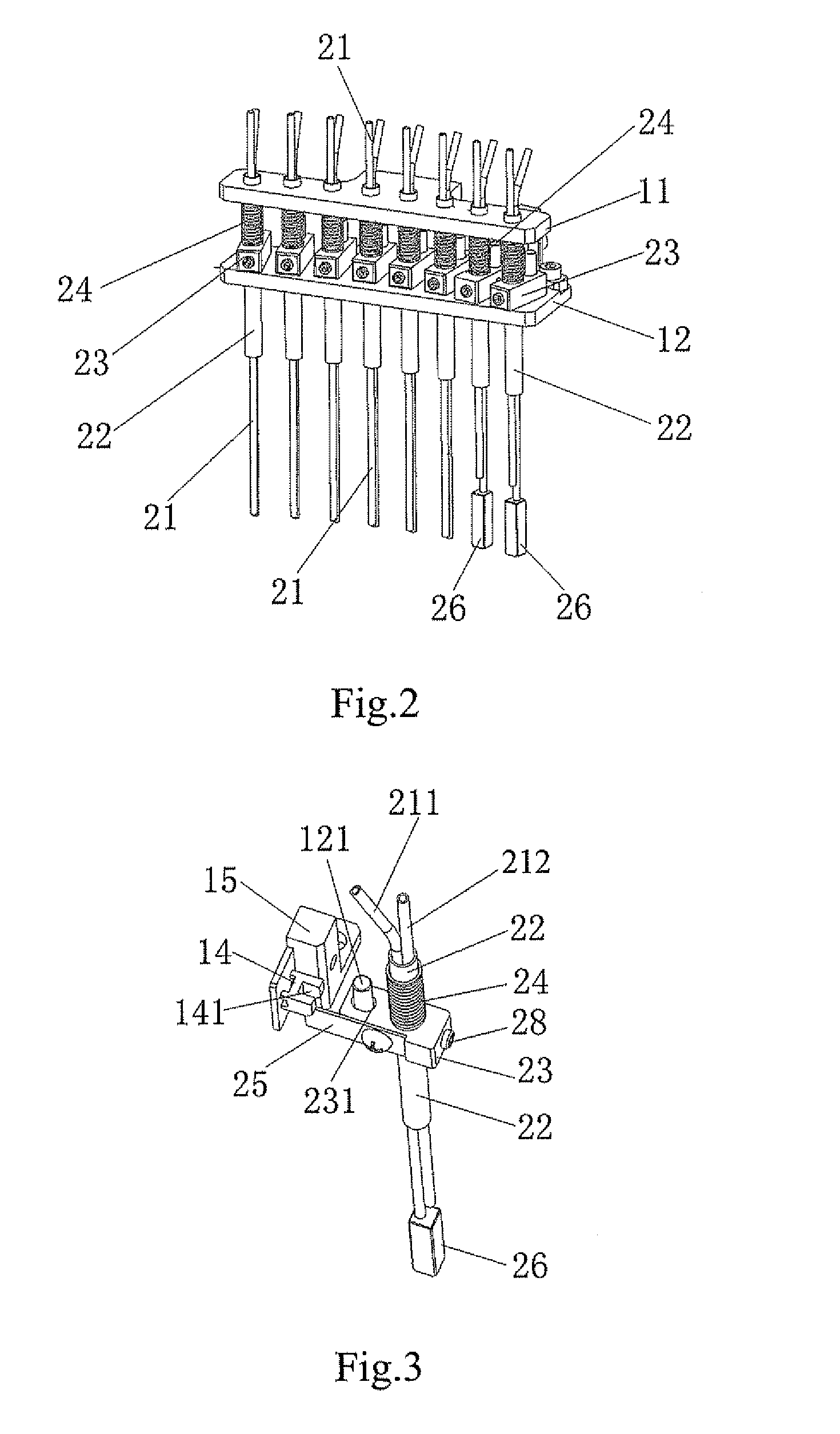
[0021]Referring to FIG. 1, in this embodiment, the reaction cuvette wash unit comprises a supporter 1 and eight sets of cleaning needle components 2 mounted on the support 1, a power unit 3 and a driving device 4. As shown in FIG. 2, the supporter 1 includes an upper supporting plate 11 and a lower supporting plate 12, which are both positioned horizontally and have a certain distance in height. The upper and lower plates 11 and 12 are fixedly joined as an integral part by a junction plate 13 positioned vertically, as shown in FIG. 4. The upper supporting plate 11 has eight upper mounting holes spaced thereon in a row, while the lower supporting plate 12 has eight lower mounting holes spaces thereon in a row. Eight upper mounting holes are aligned with those eight lower ones respectively, thus forming eight sets of mounting holes for mounting the cleaning needle components 2. The lower supporting plate 12 also provides eight locating pins 121 protruding upwardly, as shown in FIG. 3....


PUM

PropertyMeasurementUnit
elasticaaaaaaaaaa
frictionaaaaaaaaaa
weightaaaaaaaaaa

Abstract

The invention discloses a reaction cuvette wash unit comprising a cleaning needle assembly, a straight guide pair, a slide screw pair, a motor, a trigger component associated with a cleaning needle of the cleaning needle assembly in a manner to move with that cleaning needle, and a sensor used to sense the position of the trigger component. When the trigger component moves to a predetermined position, the sensor is triggered and sends a signal to a controller such that the controller controls in a manner to stop the motor. Each of cleaning needle components further comprises a sheath holder and an elastic member. The elastic member is designed to provide an elastic contact while the cleaning needles touch the bottom surface of the reaction cuvette, such that a relatively small force is exerted upon the bottom of the reaction cuvette, thereby effectively protecting the reaction cuvette from damage.

Description

STATEMENT OF RELATED APPLICATION[0001]This application claims the priority of the Chinese patent application No. 200610063323.0, filed on Oct. 26, 2006, entitled “REACTION CUVETTE WASH UNIT”, the disclosure of which is incorporated herein by reference in entirety.FIELD OF THE INVENTION[0002]The present invention relates to a wash unit for use in automated chemistry analyzer, and more particularly to a wash unit which functions cooperatively with a reaction tray in a manner to implement automatic cleaning of the reaction cuvette by a set of gas-liquid path system.BACKGROUND OF THE INVENTION[0003]The existing automatic wash unit for a full-automatic biochemical analyzer comprises a motor and multiple sets of cleaning needle components, at least one of which has a wipe nozzle. Driven by the motor, the wipe nozzle of the cleaning needle component gets access into the reaction cuvette while the reaction tray pauses, touches the bottom of the cuvette, and rises without the reaction cuvett...

Claims


Application Information

Patent Timeline
Patent Type & Authority Patents(United States)
IPC IPC(8): G01N21/00G01N35/00G01N33/00G01N31/00G01N35/08B01L3/00B01L3/02
CPCB01L99/00B01L2200/14G01N2035/0437Y10T436/119163Y10T436/11B01L3/5082B01L3/5085B01L13/02
Inventor LIU, QISONGLUO, GUOCHAO
Owner SHENZHEN MINDRAY BIO MEDICAL ELECTRONICS CO LTD
Why Eureka
Try Eureka