Thin-film transistor device and a method for manufacturing the same
a transistors, which is applied in the direction of thermoelectric device junction materials, semiconductor devices, electrical apparatus, etc., can solve the problems of inability to meet the needs of reducing power consumption or realizing sophisticated devices, and the underlying technology of thin-film transistors, so as to reduce the number of steps in manufacturing and reduce the number of steps. , the effect of low power consumption
- Summary
- Abstract
- Description
- Claims
- Application Information
AI Technical Summary
Benefits of technology
Problems solved by technology
Method used
Image
Examples
first embodiment
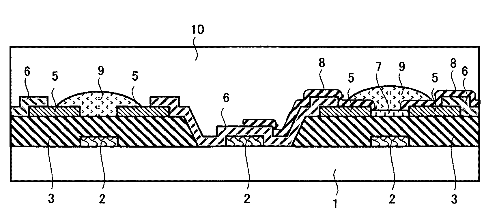
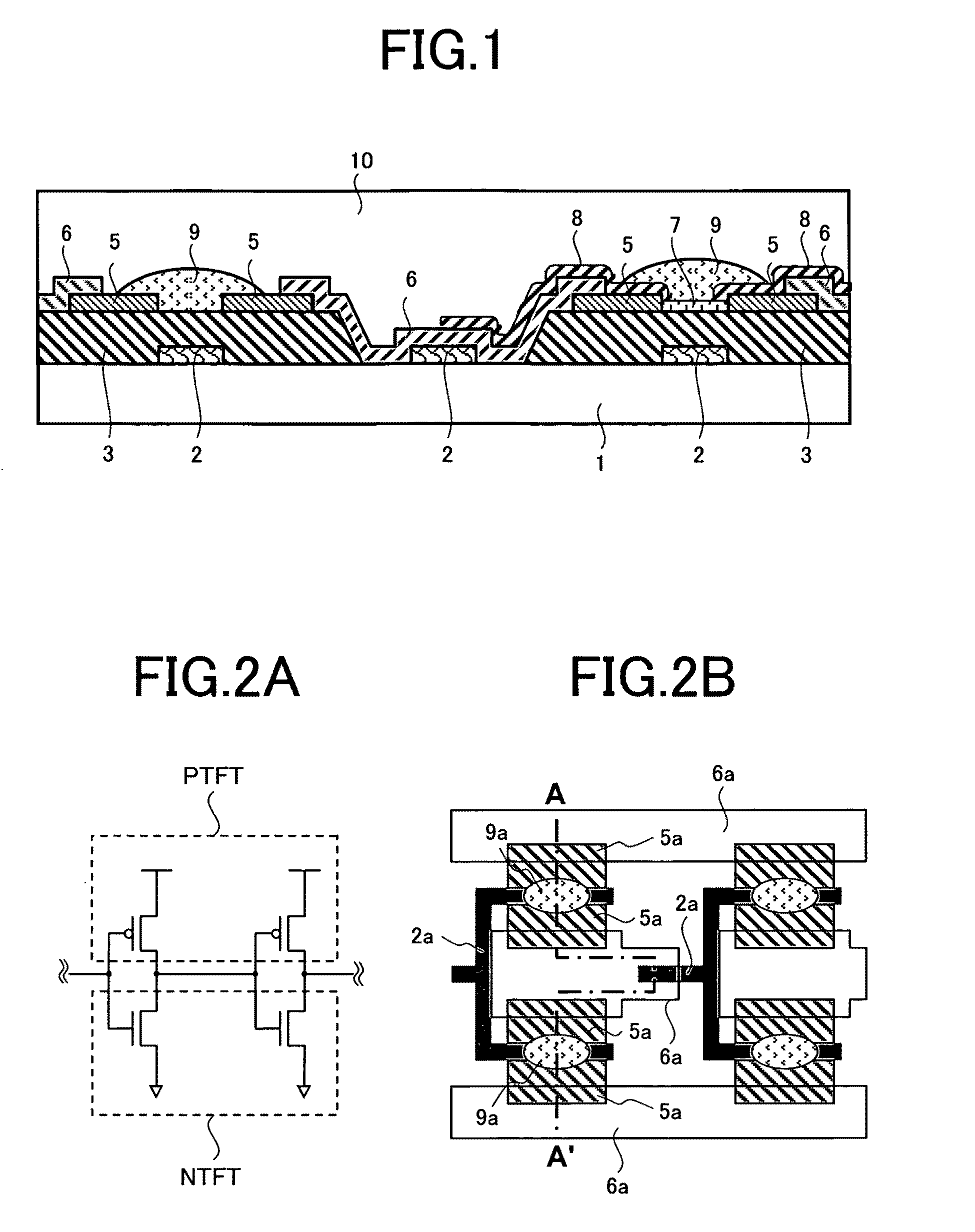
[0049]A first embodiment of the present invention is described with reference to FIGS. 1 to 10. This embodiment relates to an example of a thin film transistor formed by the solution-process and / or printable process method, for instance, on a flexible substrate in which a complementary TFT circuit is configured with a p-type TFT and an n-type TFT. The examples of circuits provided in this embodiment are a signal generator including a ring oscillator and a NAND circuit. The complementary TFT circuit as represented by the circuits operates with low power consumption, and can provide various functions or systems.
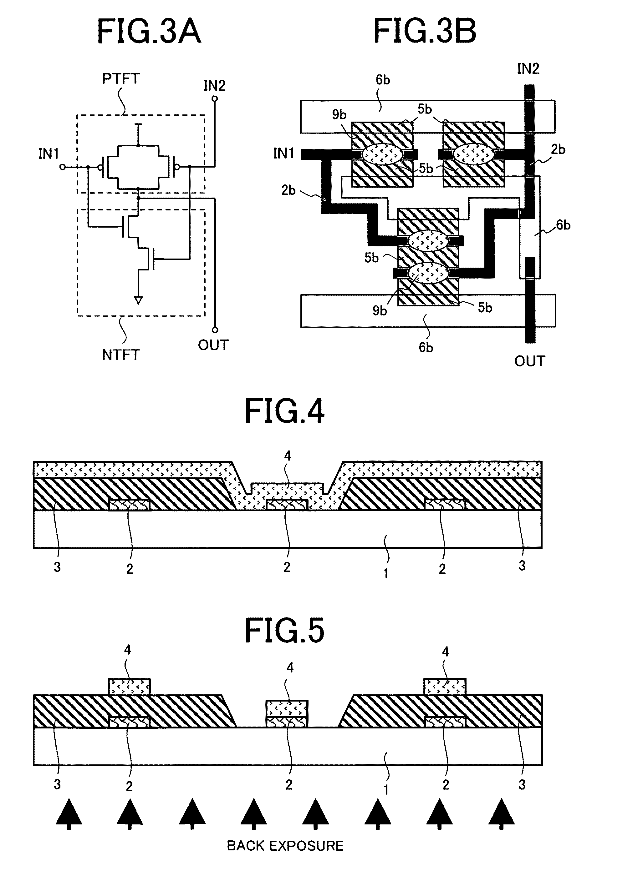
[0050]The ring oscillator has a plurality of complementary TFT invertors connected in multiple stages. FIG. 2A is a circuit diagram showing two stages of the invertors, and FIG. 2B is a plan view showing the layout. The NAND circuit shown in FIG. 3 is one of basic logic circuits required to constitute an electronic computer. FIG. 3A is a circuit diagram illustrating a two-input...
second embodiment
[0078]A second embodiment of the present invention is described with reference to FIGS. 11 to 13, and FIG. 7. The second embodiment exemplifies a tin-film transistor device on which the same complementary TFT circuit as that in the first embodiment is configured. In the second embodiment, the manufacturing steps 1 to 3 in the first embodiment shown in FIGS. 4 to 6 are replaced with those shown in FIGS. 11 to 13, and other manufacturing steps or the cross-sectional structure of the completed device as shown in FIG. 1 are the same as those in the first embodiment.
[0079]Outlines of the replaced steps are as described below.
[0080]Specifically, as shown in FIG. 11, the steps of forming the gate electrode 2 on the transparent plastic substrate 1 using a metal ink material by the print-patterning method and applying the Si oxide film 3 to provide an opening for connection are the same as the steps 1 in the first embodiment.
[0081]Then, a photo-sensitive SAM film, from which the hydrophobic ...
third embodiment
[0088]A third embodiment of the present invention is described with reference to chemical formulae 1 to 9 shown in FIG. 19 and chemical formulae 10 to 12 shown in FIG. 20. In this embodiment, example of materials for the polarizable thin films 7, 8 used in the first embodiment are shown with the chemical formulae.
[0089]Chemical formulae 1 to 7 represent examples of polarizable SAM material generating a dipole vector from the gate insulator 3 (for instance, Si oxide film) or the source / drain electrodes 5 to the organic semiconductor in the n-type TFT. In the chemical formulae, X denotes an SH group or a silane coupling group expressed by chemical formula 12. R1, R2, and R3 in chemical formula 12 denote an OCH3 group, an OCH2CH3 group or an OH group, or CL (chlorine). The polarizable thin film material adheres to electrodes when X is an SH group, and generates a dipole vector from the source / drain electrode to the organic semiconductor 9. When X is a silane coupling group, the thin fi...
PUM
 Abstract
Description
Claims
Application Information
 - R&D
- Intellectual Property
- Life Sciences
- Materials
- Tech Scout
- Unparalleled Data Quality
- Higher Quality Content
- 60% Fewer Hallucinations
Browse by: Latest US Patents, China's latest patents, Technical Efficacy Thesaurus, Application Domain, Technology Topic, Popular Technical Reports.
© 2025 PatSnap. All rights reserved.Legal|Privacy policy|Modern Slavery Act Transparency Statement|Sitemap|About US| Contact US: help@patsnap.com


