Method and system for transmit scheduling for multi-layer network interface controller (NIC) operation

a network interface controller and multi-layer technology, applied in the field of network interface processing, can solve the problems of increasing the cost of memory, increasing the cost of power, cooling and/or component costs, both within and outside the system, and not taking into account the traffic needs of adjacent nic devices. achieve the effect of low latency traffic and low latency transmission

Inactive Publication Date: 2011-08-30
AVAGO TECH INT SALES PTE LTD
View PDF9 Cites 5 Cited by
  • Summary
  • Abstract
  • Description
  • Claims
  • Application Information

AI Technical Summary

Problems solved by technology

Each NIC in this solution may not take the traffic needs of adjacent NIC devices into account.
In addition, costs for power, cooling, and / or component costs, both within and outside the system, may be considerable.
A second problem may arise since all offloads of L4 and above must meter out the transmit bandwidth between many different connections.
Furthermore, busy connection(s) may operate for long periods and the small connections with sparse amounts of traffic may not be permitted to transmit until the busy connections have become idle.
This may occur because system performance is normally sensitive to throughput for high bandwidth connections while latency is important for connections with a sparse amount of traffic, or because the system may have a policy of sending all the data available for a connection or very large blocks of data per connection.
One problem with this acceleration is that it is more important to keep the accelerated NIC transmitter updated as to the buffer status on the receiving NIC.
This may require more costly memory either in the offload NIC or in the host of the receiver, to achieve the higher throughput.
The increased window size may consume more receiver memory.
Any additional delay in generation of ACK packets, therefore, may further reduce the connection bandwidth.

Method used


Image

  • Method and system for transmit scheduling for multi-layer network interface controller (NIC) operation
  • Method and system for transmit scheduling for multi-layer network interface controller (NIC) operation
  • Method and system for transmit scheduling for multi-layer network interface controller (NIC) operation

Examples


Embodiment Construction

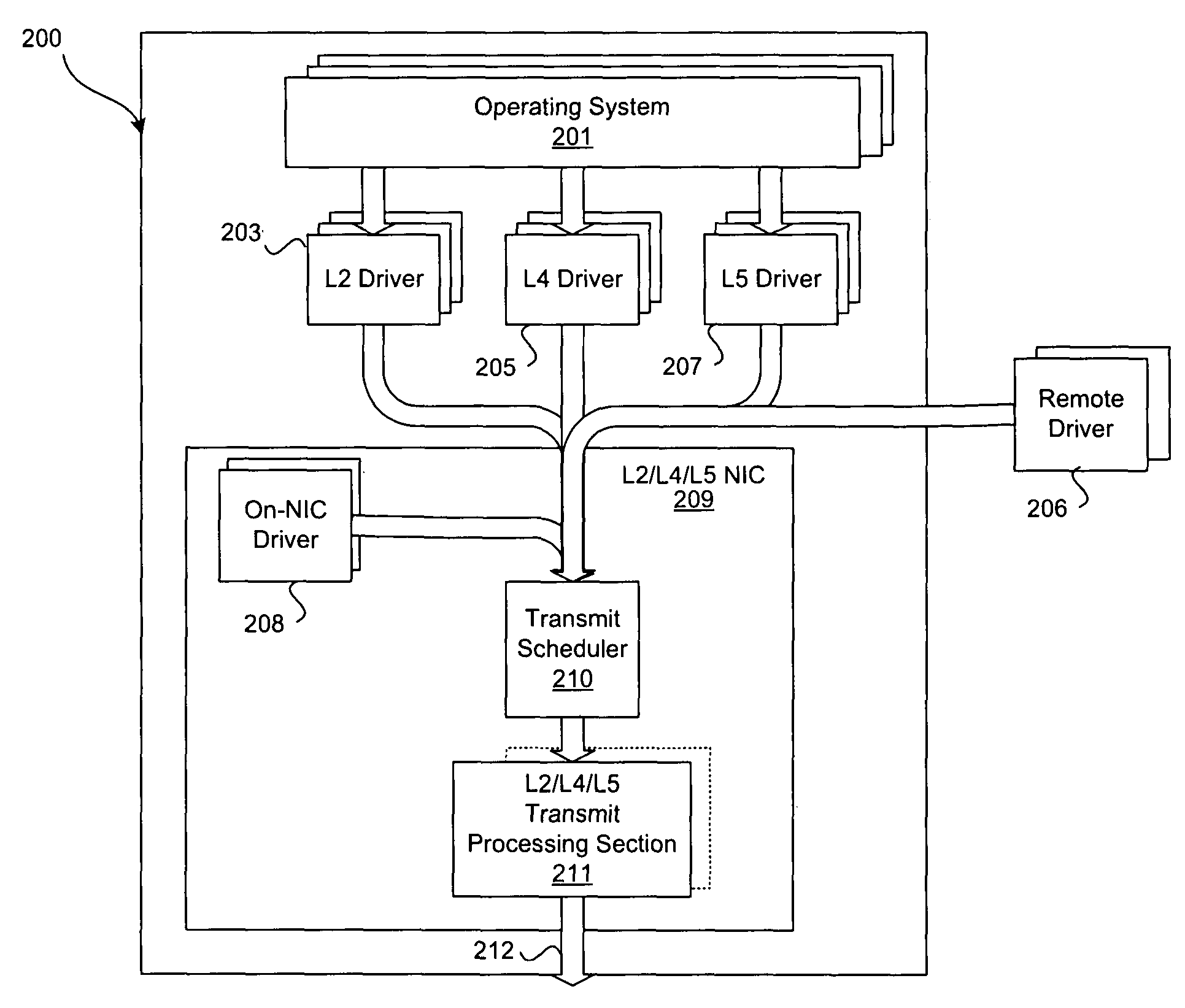
[0032]Certain embodiments of the invention may be found in a method and system for transmit scheduling for multi-layer network interface controller (NIC) operation. In one embodiment of the present invention, transmit (TX) buffer indicators may be generated, where each may identify transmit-ready data of a level 2 (L2) type, a level 4 (L4) type, and / or a level 5 (L5) type. A TX buffer indicator may be communicated from the driver to the NIC to indicate transmit-ready data. Each TX buffer indicator may contain the extent of data to transmit and may contain directly or by association a priority characteristic for the transmit operation. TX buffer indicators may be sorted and stored in a plurality of priority sets based on the priority characteristic. The priority characteristic may be configured based on TCP, or other transport or session layer acknowledge (ACK) message, and / or a protocol element. The priority characteristic may be configured based on connection requirements such as l...


PUM


Abstract

Certain embodiments of the invention may be found in a method and system for multi-layer network interface controller (NIC) operation. An aspect of the invention may utilize a two (2) level work-conserving scheduling system for network interface controller operation and may comprise tracking for all L4 / L5 offload connections with active transmit requirements as well as layer 2 (L2) level transmit requirements. The first level may comprise a round-robin scheme that may be utilized to select the next high priority, normal priority, and layer 2 (L2) transmit requirement independently. The send level arbitration may comprise a work-conserving programmable weighted round-robin priority scheme that may be utilized to select amongst the transmit tasks selected by the first level priority scheme.

Description

CROSS-REFERENCE TO RELATED APPLICATIONS / INCORPORATION BY REFERENCE[0001]This application makes reference to, claims priority to, and claims the benefit of U.S. Provisional Application Ser. No. 60 / 531,056, filed Dec. 19, 2003 and entitled “Transmit Scheduling Method for Multi-Layer Network Interface Card (NIC) Operation.”[0002]The above stated application is incorporated herein by reference in its entirety.FIELD OF THE INVENTION[0003]Certain embodiments of the invention relate to network interface processing. More specifically, certain embodiments of the invention relate to a method and system for transmit scheduling for multi-layer network interface controller (NIC) operation.BACKGROUND OF THE INVENTION[0004]The International Standards Organization (ISO) has established the Open Systems Interconnection (OSI) reference model. The OSI reference model provides a network design framework allowing equipment from different vendors to be able to communicate. More specifically, the OSI refe...

Claims


Application Information

Patent Timeline
Patent Type & Authority Patents(United States)
IPC IPC(8): H04J1/16H04L12/28H04L12/56H04L29/06
CPCH04L12/5693H04L29/06H04L47/10H04L47/2433H04L47/2466H04L47/522H04L47/60H04L47/621H04L47/6225H04L47/6255H04L49/351H04L69/161H04L69/163H04L49/205H04L49/254H04L49/602H04L69/16H04L69/12H04L47/50H04L47/43H04L9/40
Inventor MCDANIEL, SCOTTFAN, KAN FRANKIEZUR, URI EL
Owner AVAGO TECH INT SALES PTE LTD
Why Eureka
Try Eureka