Distributed antenna communications system

a distributed antenna and communications system technology, applied in diversity/multi-antenna systems, wireless communication, wireless communication, etc., can solve the problems of indoor communication difficulties of mobile units, and the lack of room for improvement in conventional distributed antenna systems

Active Publication Date: 2011-08-30
COMMSCOPE TECH LLC
View PDF210 Cites 237 Cited by
  • Summary
  • Abstract
  • Description
  • Claims
  • Application Information

AI Technical Summary

Problems solved by technology

While these MIMO configurations can improve communications when the mobile devices are located outdoors, signal attenuation caused by building structures (i.e. indoor penetration loss) can still result in communication difficulties for mobile units when located indoors.
However, conventional distributed antenna systems leave room for improvement.

Method used


Image

  • Distributed antenna communications system
  • Distributed antenna communications system
  • Distributed antenna communications system

Examples


Embodiment Construction

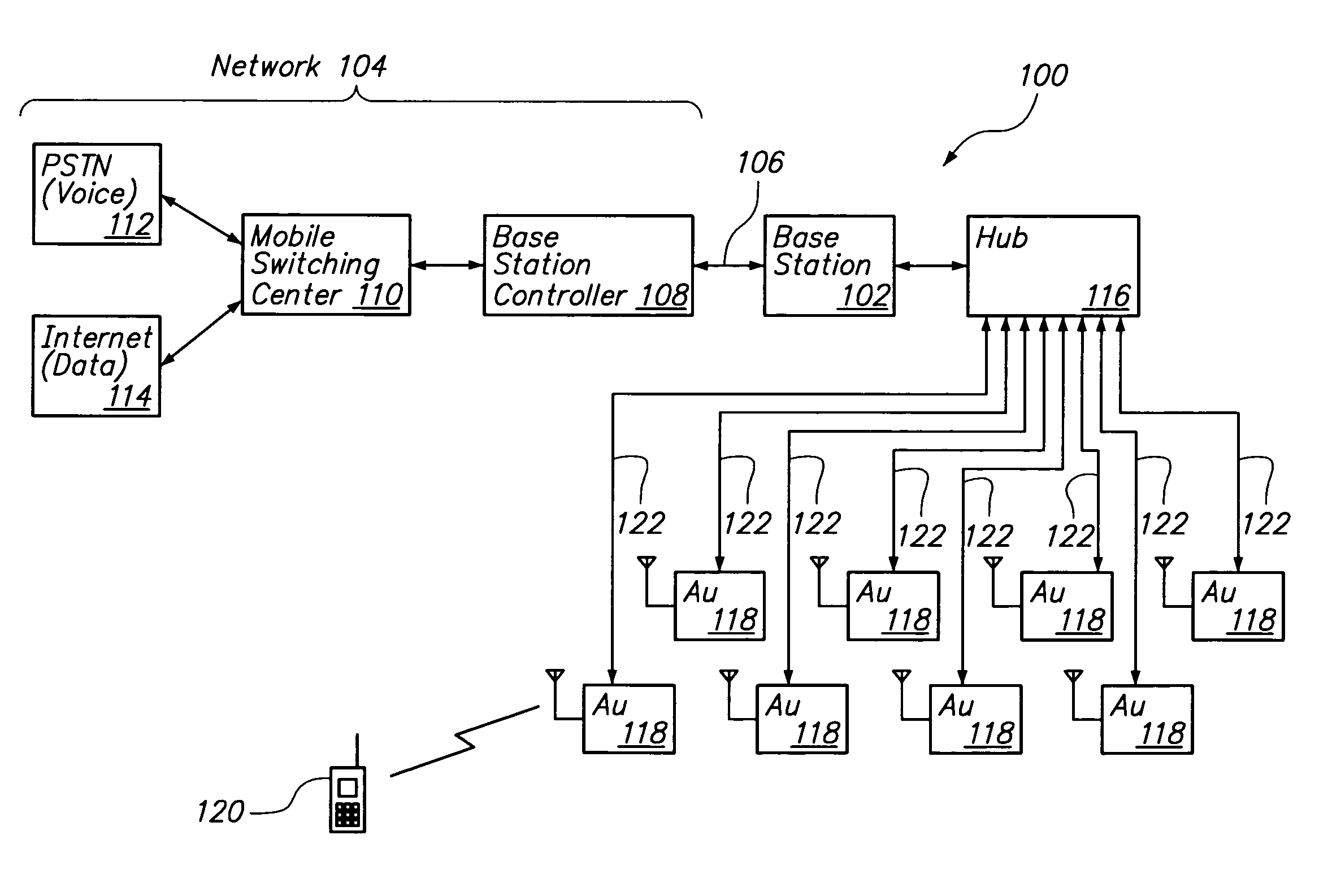
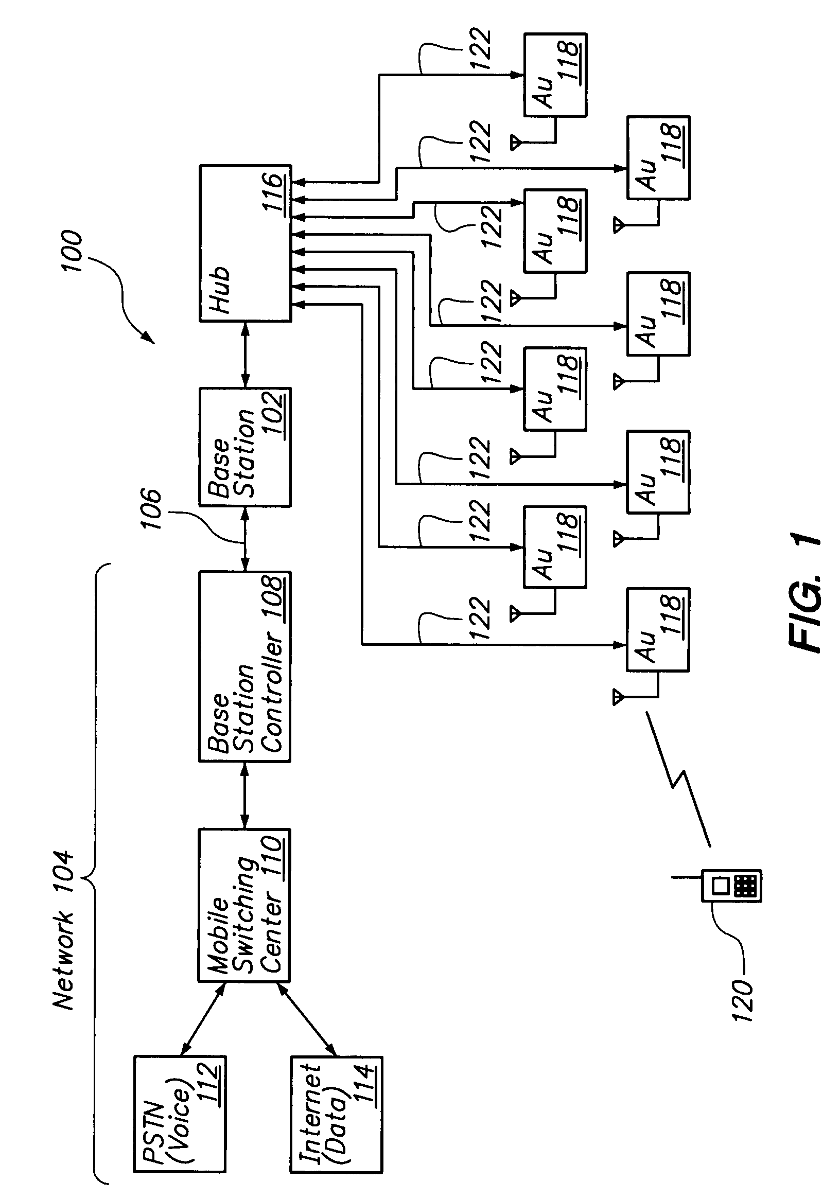
[0020]FIG. 1 illustrates a distributed antenna communications system 100 in accordance with an embodiment of the present invention. As shown in FIG. 1, a base transceiver subsystem (which may also be referred to as a BTS or base station) 102 is communicatively coupled to a communications network 104 via a backhaul link 106. Within the communications network 104, the backhaul 106 is coupled to a base station controller (BSC) 108, which is, in turn, coupled to a mobile switching center (MSC) 110. The MSC 110 is coupled to a public switched telephone network (PSTN) 112 (e.g. for voice communications) and may also be coupled the Internet 114 (e.g. for data communications).

[0021]The BSC 108 may perform various conventional functions including radio channel allocation, call handovers among base stations, configuring the base station 102, handling alarms and performing network management functions. The MSC 110 may perform various conventional functions including circuit switching, and prov...


PUM


Abstract

A distributed antenna system comprises a base transceiver station, a plurality of distributed antenna units and a signal routing apparatus. The base transceiver station has a plurality of output ports that generate a plurality of downlink signals having overlapping transmit frequencies and containing different communication content. The different communication content is directed toward each of a plurality of mobile units. The base transceiver station also has at least one uplink receive port that receives an uplink signal. The uplink signal includes communication content received from at least one of the mobile units. The plurality of distributed antenna units have coverage areas that are non-overlapping or only partially overlapping. The signal routing apparatus routes the downlink signals to the plurality of distributed antennas such that each of the plurality of downlink signals are transmitted by one or more of the distributed antennas and each distributed antenna only transmits one of the downlink signals.

Description

FIELD OF THE INVENTION[0001]The present invention relates to wireless communications and, more particularly, to a distributed antenna system for wireless communications.BACKGROUND OF THE INVENTION[0002]In a conventional wireless cellular telephone network, base transceiver stations (BTS) facilitate communication between mobile units (e.g. cellular telephones) and the telephone network. A typical base station comprises multiple transceiver units and antennas for sending radio signals to the mobile units (downlink) and for receiving radio signals from the mobile units (uplink). The antennas of the base station are positioned outdoors on a cellular tower or on top of a building. Base stations are strategically located so as to maximize communications coverage over large geographical areas. The base stations are communicatively coupled to the telephone network via backhaul connections.[0003]Conventional base stations have employed one transmit output signal and one receive signal for ea...

Claims


Application Information

Patent Timeline
Patent Type & Authority Patents(United States)
IPC IPC(8): H04W36/00H04W88/08
CPCH04B7/0874H04B7/0691H04W88/085
Inventor SCHEINERT, STEFAN
Owner COMMSCOPE TECH LLC
Why Eureka
Try Eureka