Collision detector

a detector and occupant technology, applied in the field of collision detectors, can solve the problems of erroneous activation of the airbag system, and erroneous activation of the airbag module, so as to prevent erroneous operation of reliably activate the occupant protector unit

Inactive Publication Date: 2011-08-30
CALSONIC KANSEI CORP
View PDF14 Cites 184 Cited by
  • Summary
  • Abstract
  • Description
  • Claims
  • Application Information

AI Technical Summary

Benefits of technology

[0026]In view of solving the above problems, an object of the present invention is to provide a collision detector which can reliably activate an occupant protector unit such as an airbag at a vehicle collision, and prevent erroneous operation of the occupant protector unit due to electric noises.

Problems solved by technology

The prior art collision detector 1 has a problem that these electric noises may enter signal paths between the acceleration sensors S1, S2 and the comparator 2, and cause erroneous activation of the airbag module 5.
The airbag system originally aims to protect occupants from a vehicle collision, however, the airbag system may be erroneously activated during vehicle running.
This may cause a problem of erroneously activating the airbag module 5 since the potential difference V+− is a large value as shown in FIG. 4C.

Method used


Image

  • Collision detector
  • Collision detector
  • Collision detector

Examples


first embodiment

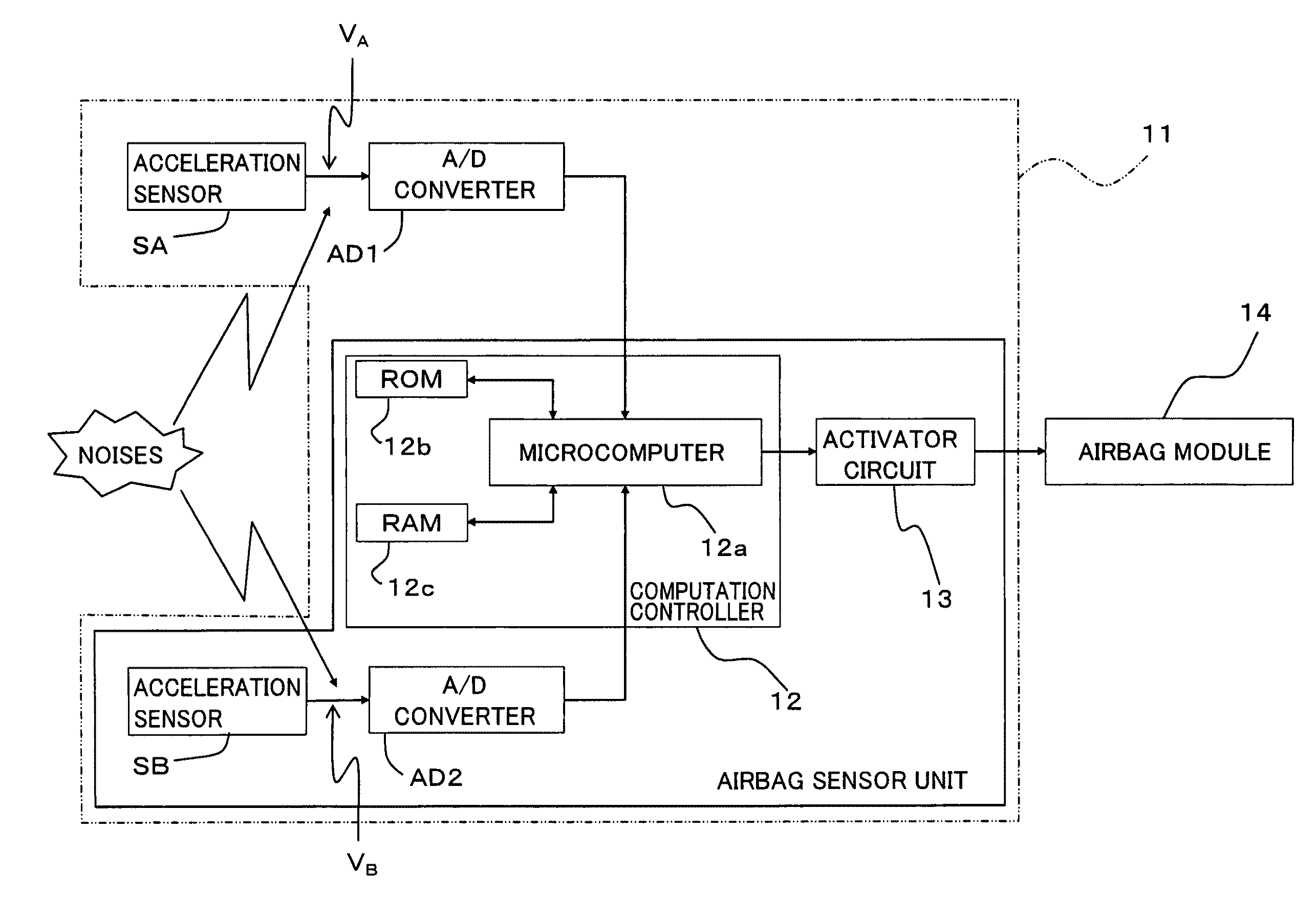
[0048]FIG. 5A shows a collision detector 11 according to a first embodiment of the present invention which is placed in a center console C between a driver's seat VS1 and a passenger's seat VS2.

[0049]In FIG. 6, the collision detector 11 comprises acceleration sensors SA, SB, A / D converters AD1, AD2, a computation controller 12, and an activator circuit 13.

[0050]An airbag module 14 (occupant protector unit) is provided in the center of a steering wheel, for example and mainly comprised of an airbag and an inflator which expands the airbag.

[0051]As shown in FIG. 5B, the collision detector 11 according to the present embodiment is configured to detect a vehicle collision based on acceleration data detected by the acceleration sensors SA, SB mounted on a circuit board 11a of the collision detector 11, in order to activate the airbag module 14.

[0052]In the present embodiment, the acceleration sensors SA, SB each incorporate an amplifier to detect acceleration of the vehicle at their resp...

second embodiment

[0122]In the second embodiment, a description will be mainly made on a portion different from the first embodiment, and the same components as those in the first embodiment will be given the same numeric codes so that a description thereon will be omitted.

[0123]Although the first embodiment has not described a type of vehicle collision such as a front collision and a rear collision, needless to say that the front and rear collisions cause different variations in profiles of the detected accelerations aA, aB of the acceleration sensors SA, SB. The first and second collision determination processes in the first embodiment use profile data on acceleration variation at a rear collision. Thus, the collision detector 11 according to the first embodiment is configured to activate the airbag module 14 upon satisfaction of a predetermined condition for a rear collision.

[0124]However, the activation timing for the airbag module 14 at a rear collision needs to be slightly delayed from that at ...


PUM


Abstract

A vehicle collision detector is configured to reliably activate an airbag system at a collision and prevent the airbag system from erroneously operating. The collision detector includes two acceleration sensors disposed at different positions in a vehicle to detect acceleration for collision determination, first and second collision routines in which a determination is made on whether or not a variation in the detected acceleration is caused by a collision, and a final collision routine in which an airbag module is activated when all of results of the first and second collision routines indicate a collision.

Description

CROSS REFERENCE TO RELATED APPLICATION[0001]The present application is based on and claims priority from Japanese Patent Application No. 2008-39277, filed on Feb. 20, 2008 and No. 2009-10722, filed on Jan. 21, 2009, the disclosure of which is hereby incorporated by reference in its entirety.BACKGROUND OF THE INVENTION[0002]1. Field of the Invention[0003]The present invention relates to a collision detector which detects a collision of an automobile.[0004]2. Description of the Related Art[0005]In the prior art, a collision detector to detect a collision of an automobile is known (disclosed in Japanese Unexamined Patent Application Publication No. Hei 3-20674, for example).[0006]Recently, an automobile is equipped with an occupant protector unit such as an airbag system in order to secure safety of occupants at a collision.[0007]The airbag system is configured to explode an airbag in receiving a high impact over a predetermined amount of force and use it for a cushion for the head of ...

Claims


Application Information

Patent Timeline
Patent Type & Authority Patents(United States)
IPC IPC(8): B60R21/013
CPCB60R21/0132B60R21/0136B60R2021/0117B60R21/01332
Inventor OOWADA, TOHRU
Owner CALSONIC KANSEI CORP
Why Eureka
Try Eureka