
Decimated bisectional pitch refinement

a decimated bisectional and pitch refinement technology, applied in the field of decimated bisectional pitch refinement, can solve the problems of complex pitch refinement steps, frame corruption, loss, etc., and achieve the effect of low complexity

Active Publication Date: 2011-08-30
AVAGO TECH INT SALES PTE LTD
View PDF16 Cites 6 Cited by
  • Summary
  • Abstract
  • Description
  • Claims
  • Application Information

AI Technical Summary

Benefits of technology

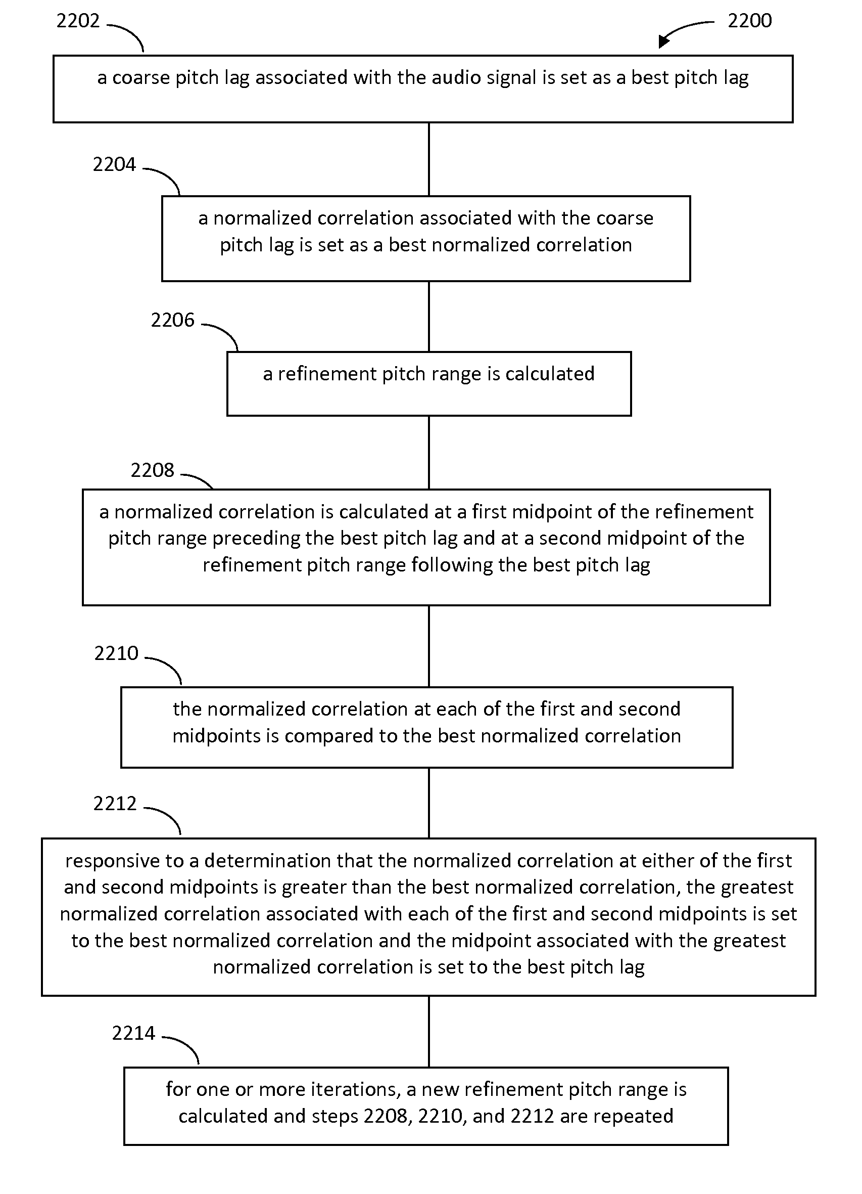
The present invention provides a method for refining the pitch of a signal using a combination of signal decimation and a bisectional search of the correlation around the coarse pitch lag. This method has low complexity and can be applied to various fields where parameters can be estimated from a down-sampled version of an original signal. The technique involves decimating the signal to reduce complexity and using a bisectional search to refine the pitch until an acceptable tolerance is reached. The method can be used in areas where the pitch is not the only parameter being refined.

Problems solved by technology

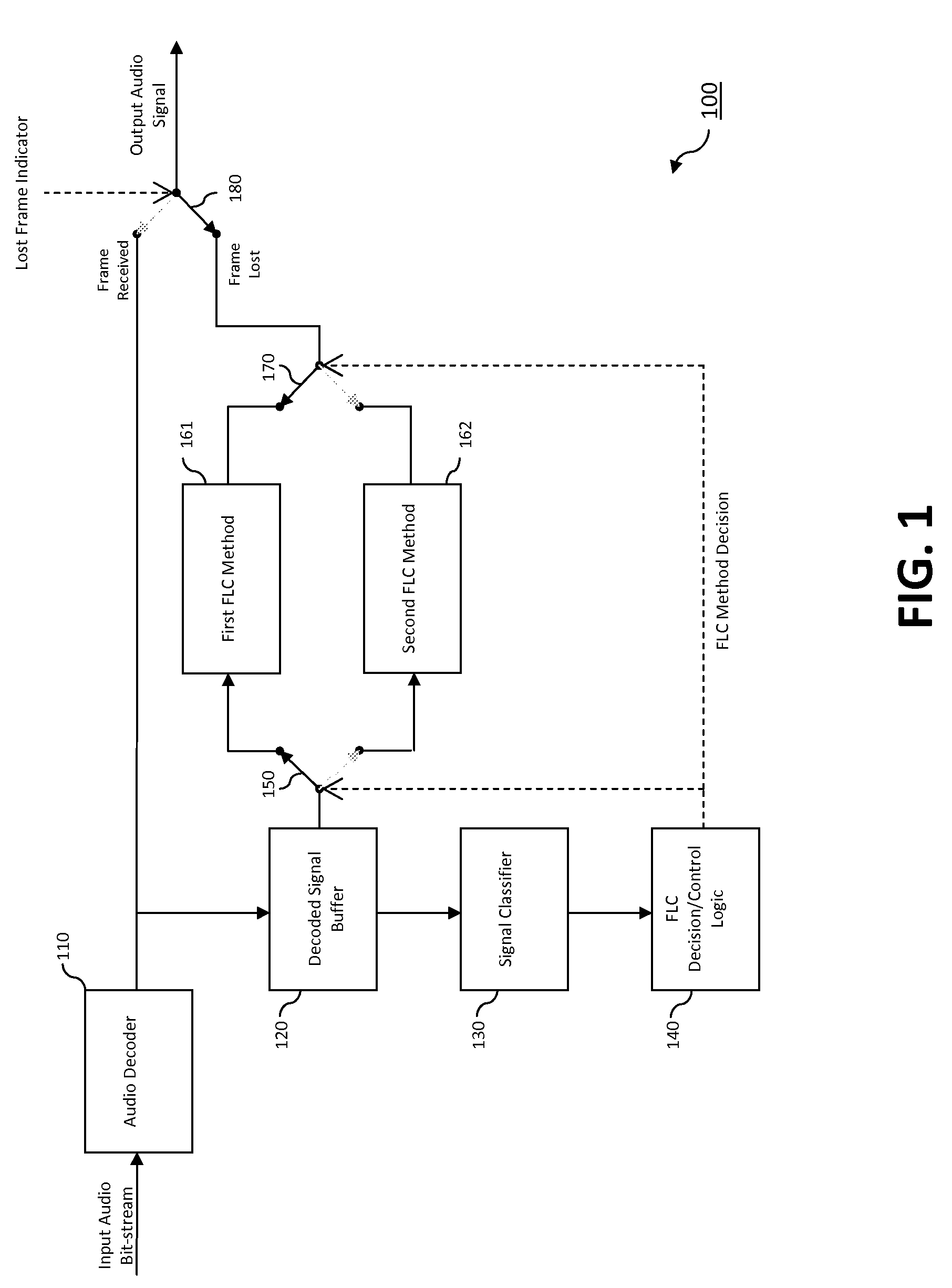
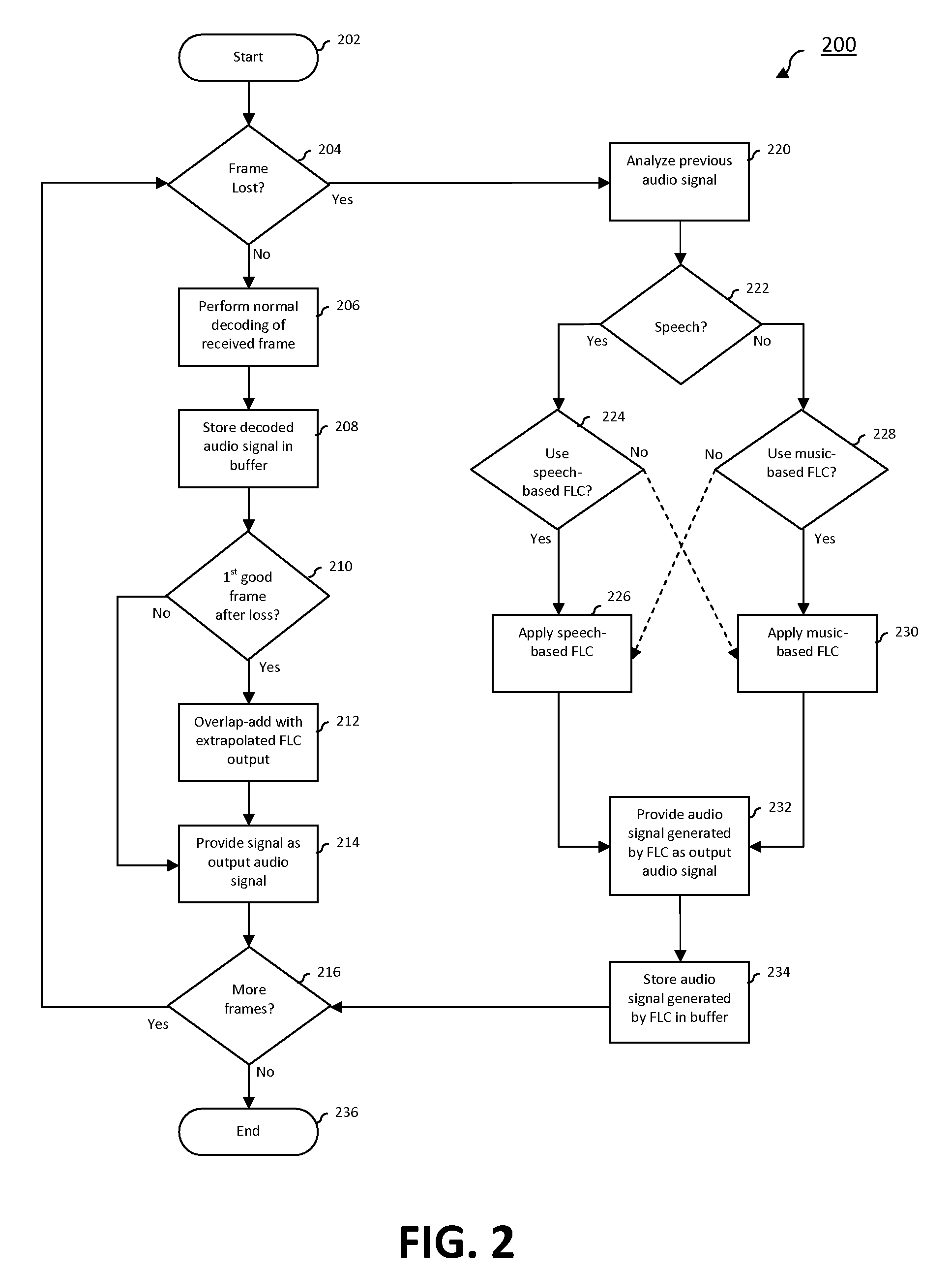
During storage or transmission, the frames may be corrupted, lost, or received too late for playback.
Without regard for complexity, these straightforward approaches can be very complex.
However, the pitch refinement step may present a significant complexity load in itself, depending on the accuracy of the coarse pitch.

Method used


Image

  • Decimated bisectional pitch refinement
  • Decimated bisectional pitch refinement
  • Decimated bisectional pitch refinement

Examples


first embodiment

1. First Embodiment

Overlapping Decomposed Signals with Decomposed Signals

[0238]In this embodiment, the signals for overlapping are decomposed into a correlated component, scout and scin, and an uncorrelated component, suout and suin. The overlapped signal s(n) is then given by the following equation (Equation C.1):

s(n)=[scout(n)·wcout(n)+scin(n)·wcin(n)]+n=0 . . . N−1

[suout(n)·wuout(n)+suin(n)·wuin(n)]

[0239]FIG. 16 shows a flowchart 1600 providing example steps for overlapping a first decomposed signal with a second decomposed signal according to the above Equation C.1. The steps of flowchart 1600 need not necessarily occur in the order shown in FIG. 16. Other structural and operational embodiments will be apparent to persons skilled in the relevant art(s) based on the discussion provided herein. For example, FIG. 17 shows a system 1700 configured to implement Equation C.1, according to an embodiment of the present invention. Flowchart 1600 is described as follows with respect to FI...

second embodiment

2. Second Embodiment

Overlapping a Mixed Signal with a Decomposed Signal

[0244]In this embodiment, one of the overlapping signals (in or out) is decomposed while the other signal has the correlated and uncorrelated components mixed together. Ideally, the mixed signal is first decomposed and the first embodiment described above is used. However, signal decomposition is very complex and overkill for most applications. Instead, the optimal overlapped signal may be approximated by the following equation (Equation C.2.a):

s(n)=[sout(n)·wcout(n)]·β+scin(n)·wcin(n)+n=0 . . . N−1

[sout(n)·wuout(n)]·(1−β)+suin(n)·wuin(n)

where β is the desired fraction of correlated signal in the final overlapped signal s(n), or an estimate of the cross-correlation between sout and scin+suin. The above formulation is given for a mixed sout signal and decomposed sin signal. A similar formulation for the opposite case, where sout is decomposed and Sin is mixed, is provided by the following equation (Equation C.2.b)...

third embodiment

3. Third Embodiment

Overlapping a Mixed Signal with a Mixed Signal

[0252]In this embodiment, both overlapping signals are not decomposed. Once again, a desired solution is to decompose both signals and use the first embodiment of subsection C.1 above. However, for most applications, this is not required. In an embodiment, an adequate compromise solution is given by the following equation (Equation C.3):

s(n)=[sout(n)·wcout(n)+sin(n)·wcin(n)]β+n=0 . . . N−1

[sout(n)·wuout(n)+sin(n)·wuin(n)]·(1−β)

where β is an estimate of the cross-correlation between sout and sin. Again, notice that if the signals are completely correlated (β=1) or completely uncorrelated (β=0), the solution is optimal.

[0253]FIG. 20 shows a flowchart 2000 providing example steps for overlapping a mixed first signal with a mixed second signal according to the above Equation C.3. The steps of flowchart 2000 need not necessarily occur in the order shown in FIG. 20. Other structural and operational embodiments will be appare...


PUM


Abstract

A method and system for refining an estimated pitch period estimate based on a coarse pitch useful for performing frame loss concealment in an audio decoder as well as for other applications. A normalized correlation at the coarse pitch lag is computed and used as the current best candidate. The normalized correlation is then evaluated at the midpoint of the refinement pitch range on either side of the current best candidate. If the normalized correlation at either midpoint is greater than the current best lag, the midpoint with the maximum correlation is selected as the current best lag. After each iteration, the refinement range is decreased by a factor of two and centered on the current best lag. This bisectional search continues until the pitch has been refined to an acceptable tolerance or until the refinement range has been exhausted. During each step of the bisectional pitch refinement, the signal is decimated to reduce the complexity of computing the normalized correlation.

Description

CROSS-REFERENCE TO RELATED APPLICATIONS[0001]This application claims priority to provisional U.S. Patent Application No. 60 / 835,097, filed Aug. 3, 2006, the entirety of which is incorporated by reference herein.BACKGROUND OF THE INVENTION[0002]1. Field of the Invention[0003]The present invention relates to a method for estimating a pitch period in a system for coding and decoding speech and / or audio signals.[0004]2. Background Art[0005]In the field of speech coding, nearly all speech codecs require an estimate of the pitch period. During the encoding process, most of the popular predictive speech coding schemes, such as Code-Excited Linear Prediction (CELP) and Multi-Pulse Linear Predictive Coding (MPLPC) exploit the long-term correlation between speech samples at the pitch period present during voiced speech. Transform-based speech coding schemes such as Sinusoidal Transform Coding (STC) typically analyze the speech in the frequency-domain and extract a model-based set of parameter...

Claims


Application Information

Patent Timeline
Patent Type & Authority Patents(United States)
IPC IPC(8): G10L11/04G10L19/00G10L11/00G10L19/14G10L25/90
CPCG10L19/005G10L25/90
Inventor ZOPF, ROBERT W.
Owner AVAGO TECH INT SALES PTE LTD
Learn More