Dry shaver

a shaver and shaver technology, applied in the field of dry shavers, can solve the problems of irritation of the skin, inability to make smooth shaving, and inability to achieve smooth shaving, so as to achieve more effective close shaving

Active Publication Date: 2011-09-06
MATSUSHITA ELECTRIC WORKS LTD
View PDF25 Cites 12 Cited by
  • Summary
  • Abstract
  • Description
  • Claims
  • Application Information

AI Technical Summary

Benefits of technology

[0004]Thus, the skin guard blocks the skin from entering into a recess between the finishing cutter and the adjacent cutter, thereby avoiding the skin from being pressed excessively against the side of the finishing cutter, i.e., an ineffective cutting zone when moving the shaving head across the skin with the first outer cutter leading in the moving direction, and therefore assuring a smooth close shaving without irritating the skin.
[0005]Preferably, the skin guard is floatingly supported to a frame of the shaving head and is spring-biased for pressed contact with the user's skin. Thus, the skin guard can be easily to follow the skin while the shaving head is manipulated to move across the skin, minimizing to drag the skin and therefore assuring a comfortable shaving.
[0008]In a preferred embodiment, the shaving head additionally carries a slit cutter which is interposed between the finishing cutter and the second outer cutter to define another skin guard which blocks the skin from entering a recess between the finishing cutter and the second outer cutter, also for blocking the skin from contacting the side of the finishing semi-cylindrical cutter. The slit cutter is composed of an elongated outer blade with a number of slits opened at lateral edges of the outer blade, and an inner cutter driven by the motor to move in sliding contact with the outer blade. The outer blade is also supported to the frame, while the finishing foil and the slit cutter are floatingly supported to the frame and are spring biased for pressed contact with the user's skin. With this structure, the slit cutter acting as the skin guard can be depressed together with the finishing cutter and can be therefore kept in optimum contact with the skin, assuring to move the shaving head across the skin smoothly.
[0010]Further, the outer blade may be coupled to the finishing foil by means of an adjustor spring so as to be urged from the finishing foil in a direction of being pressed against the user's skin. The adjustor spring generates a counter-spring force acting on the finishing cutter to reduce the spring-bias given per set thereto, thereby realizing the suitably adjusted spring-biases respectively to the finishing cutter and the slit cutter.
[0011]Moreover, the finishing foil may be configured to have a region where each of the perforations is surrounded partly by a thin section and partly by a thick section. The thin section gives an increased chance of introducing the hairs deep into the associated perforation for more effective close shaving.

Problems solved by technology

Although it is found effective to make the intended shaving, the finishing cutter is likely to be pressed excessively at its one side when the shaving head is moving across the skin in a direction perpendicular to the length of the cutter, thereby causing skin irritation or even causing the skin to be cut.
In other words, the deeply curved finishing cutter has an effective cutting zone only around its tip and is not successful to make smooth shaving free from pain at its side zones remote from the tip.
Accordingly, when the deeply curved finishing cutter is interposed between the other cutters to project to a greater extent than the others, as seen in U.S. Pat. No. 5,185,926, there is always a risk of pressing the skin excessively at the side of the cutter and irritating the skin.

Method used


Image

  • Dry shaver
  • Dry shaver
  • Dry shaver

Examples


Embodiment Construction

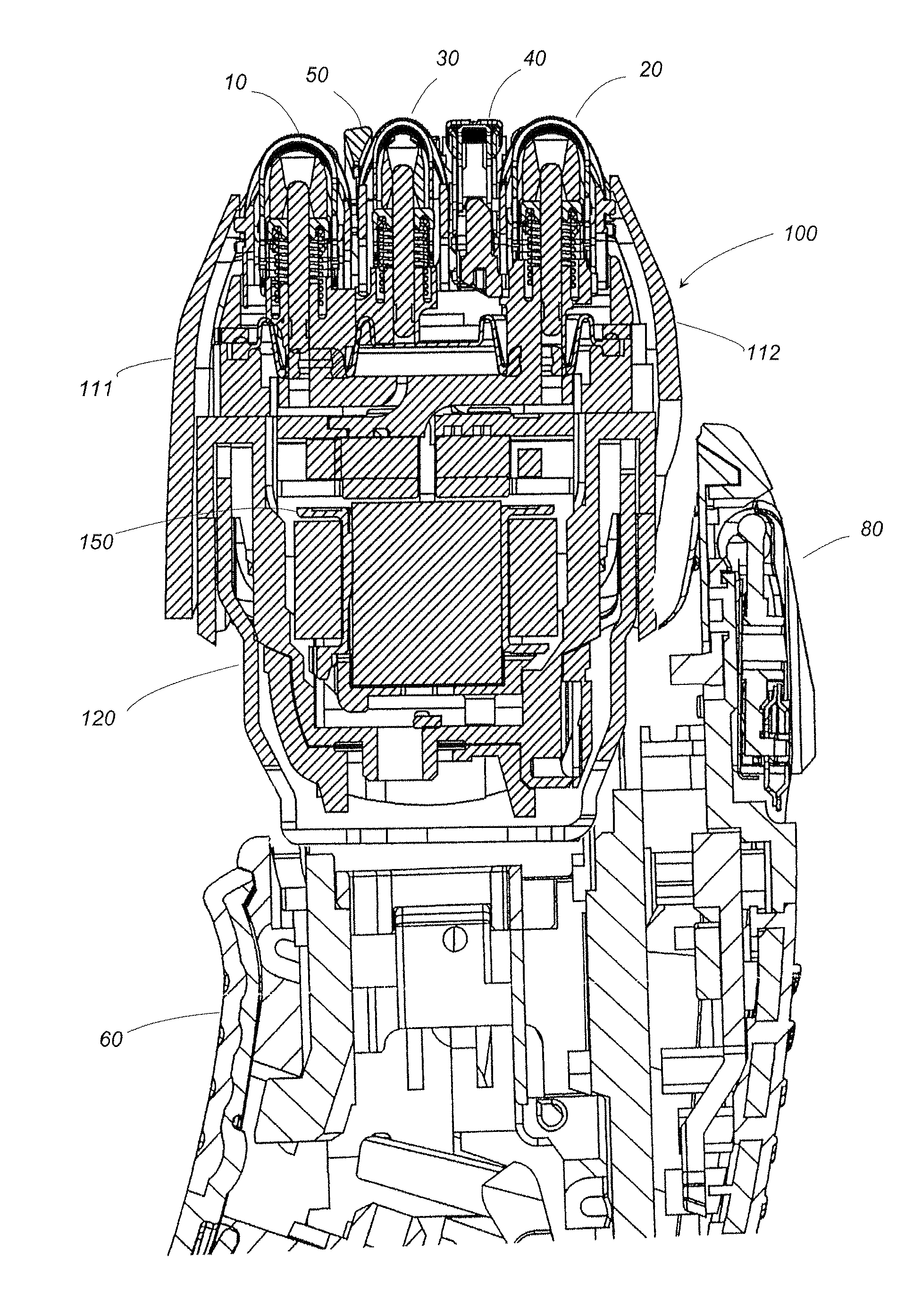
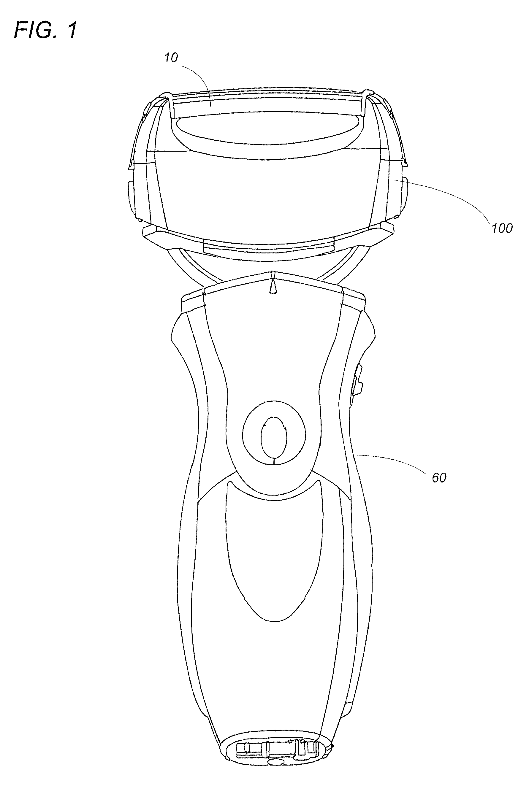
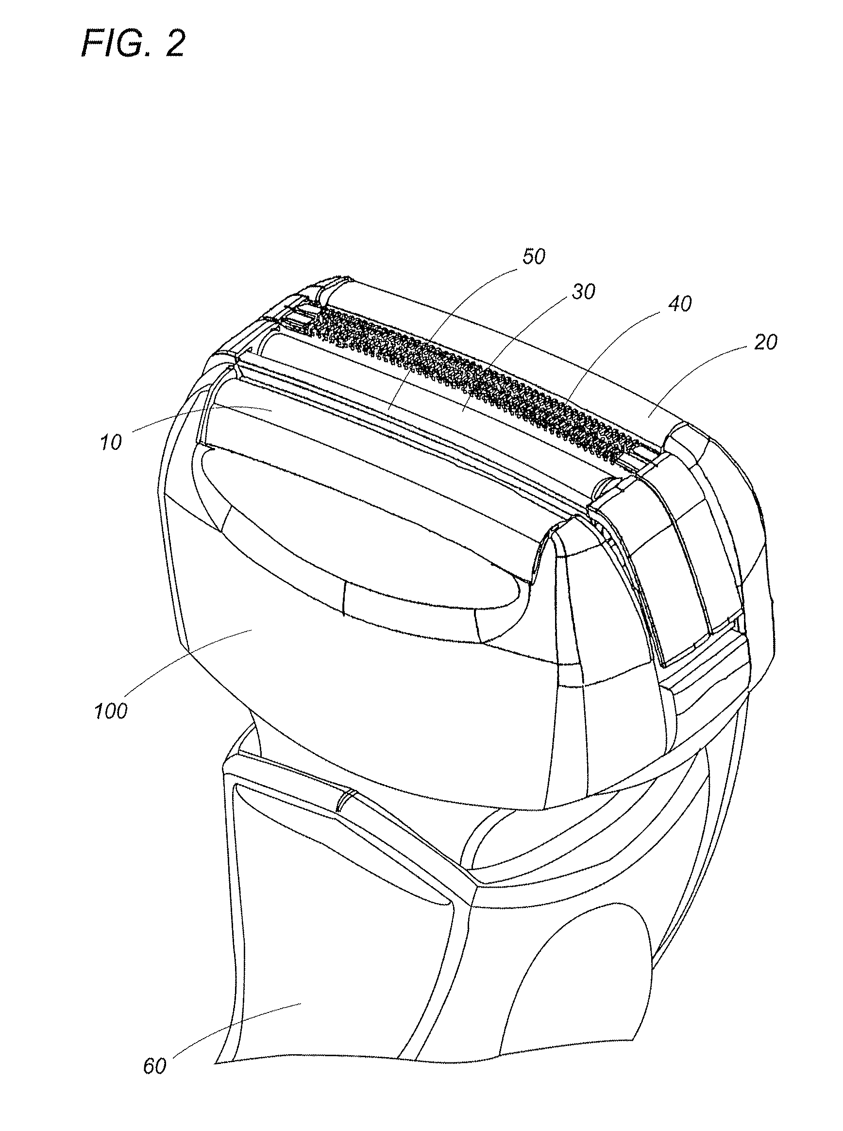
[0028]Referring now to FIGS. 1 to 5, there is shown a dry shaver in accordance with a preferred embodiment of the present invention. The dry shaver is composed of a hand grip 60 and a shaving head 100 mounted on top of the hand grip 60. The shaving head 100, which is elongated to have a lengthwise axis and a width axis, is connected to the grip 60 to be movable relative thereto about an axis perpendicular to the lengthwise axis. The shaving head 100 carries four differently configured cutters, namely, a semi-cylindrical first outer cutter 10, a semi-cylindrical second outer cutter 20, a semi-cylindrical finishing cutter 30, and a slit cutter 40. These cutters are all elongated along the lengthwise axis of the shaving head 100 and arranged in parallel relation with each other along the width axis.

[0029]The shaving head 100 is composed of a casing 120 and a frame 130 detachable to the casing 120. The casing 120 is of a water-proof structure accommodating therein a linear motor 150 and...


PUM


Abstract

A dry shaver has an elongated shaving head with a lengthwise axis. The shaving head carries semi-cylindrical first and second outer cutters disposed on its opposite width ends, and a semi-cylindrical finishing cutter and a slit cutter interposed between the first and second outer cutters. The finishing cutter has a finishing foil which is deeply curved than a foil of the first and second outer cutters into an arcuate contour having a width less than that of the first and second outer cutters. The finishing foil disposed behind the first outer cutter comes into contact with a users skin to make closer shaving than the first and second cutters. A skin guard project between the first outer cutter and the finishing cutter to protect the skin from being pressed excessively to a side of the finishing foil when moving the shaving head across a user' skin with the first outer cutter leading in a moving direction, thereby reducing skin irritation.

Description

TECHNICAL FIELD[0001]The present invention is directed to a dry shaver, more particularly a dry shaver having multiple cutters.BACKGROUND ART[0002]Japanese Patent publication no. 8-318057 and U.S. Pat. No. 5,185,926 disclose a dry shaver having three elongated semi-circular cutters which are arranged in side-by-side relation with each other. One of the cutters is designed to project to a greater extent than the other cutter to define a finishing cutter which comes first into contact with a user skin for shaving hairs on a narrow area, for example, under a nose and chip top. Although it is found effective to make the intended shaving, the finishing cutter is likely to be pressed excessively at its one side when the shaving head is moving across the skin in a direction perpendicular to the length of the cutter, thereby causing skin irritation or even causing the skin to be cut. This is particularly true, when the finishing cutter is curved more deeply than the other to have an arcuate...

Claims


Application Information

Patent Timeline
Patent Type & Authority Patents(United States)
IPC IPC(8): B26B19/04
CPCB26B19/046B26B19/10B26B19/384B26B19/42B26B19/12B26B19/04
Inventor SATO, MASAAKIIWASAKI, JYUZAEMONSHIBA, TAKESHISHIMIZU, HIROAKIKOMORI, SHUNSUKE
Owner MATSUSHITA ELECTRIC WORKS LTD
Why Eureka
Try Eureka