[0005]It is the purpose of the invention to prevent scattering of dust when sawing in materials which have a tendency to generate dust, according to other principles than those which are typical according to prior art as exemplified e.g. through the above mentioned references. While the apparatus according to WO 02 / 100597 is based on the principle of employing the entire volume of a completely shrouding blade guard as a suction box, from where the dust is sucked away via a hose connected to a vacuum source, and the apparatus according to U.S. Pat. No. 5,167,215 is based on the assumption that the saw blade has a capacity to through essentially all dust up into a “funnel” trailing after the blade guard, from where the dust is sucked away through a suction hose, the present invention is based on the principle of establishing a “mini suction box in situ” in a limited section of the kerf. This limited section comprises a front section, within which the saw blade is entered or can be entered into the kerf, and a rear section immediately behind said front section. This is achieved therein that the cutting and dust collection assembly, according to an aspect of the invention, includes a cover device which sufficiently well restricts the passages for air at the side of the saw blade and between the cover device and the surface and the work piece within the region of said restricted section of the kerf, and whereas a chamber in a terminal section of the cover device which has an outlet opening, which can be or is connected to a vacuum source, is provided with an inlet port which is provided and positioned such that it is shrouded relative to environment, can be connected to said “mini suction box”, i.e. to the restricted region of the kerf, preferably to its said rear section. By means of an assembly which is equipped in that way and by means of a working machine which is provided with an assembly equipped in that way, a primary objective of the invention can be satisfied, namely to efficiently collect and remove the dust which is generated in connection with sawing in concrete and other materials which have a tendency to cause dust formation.
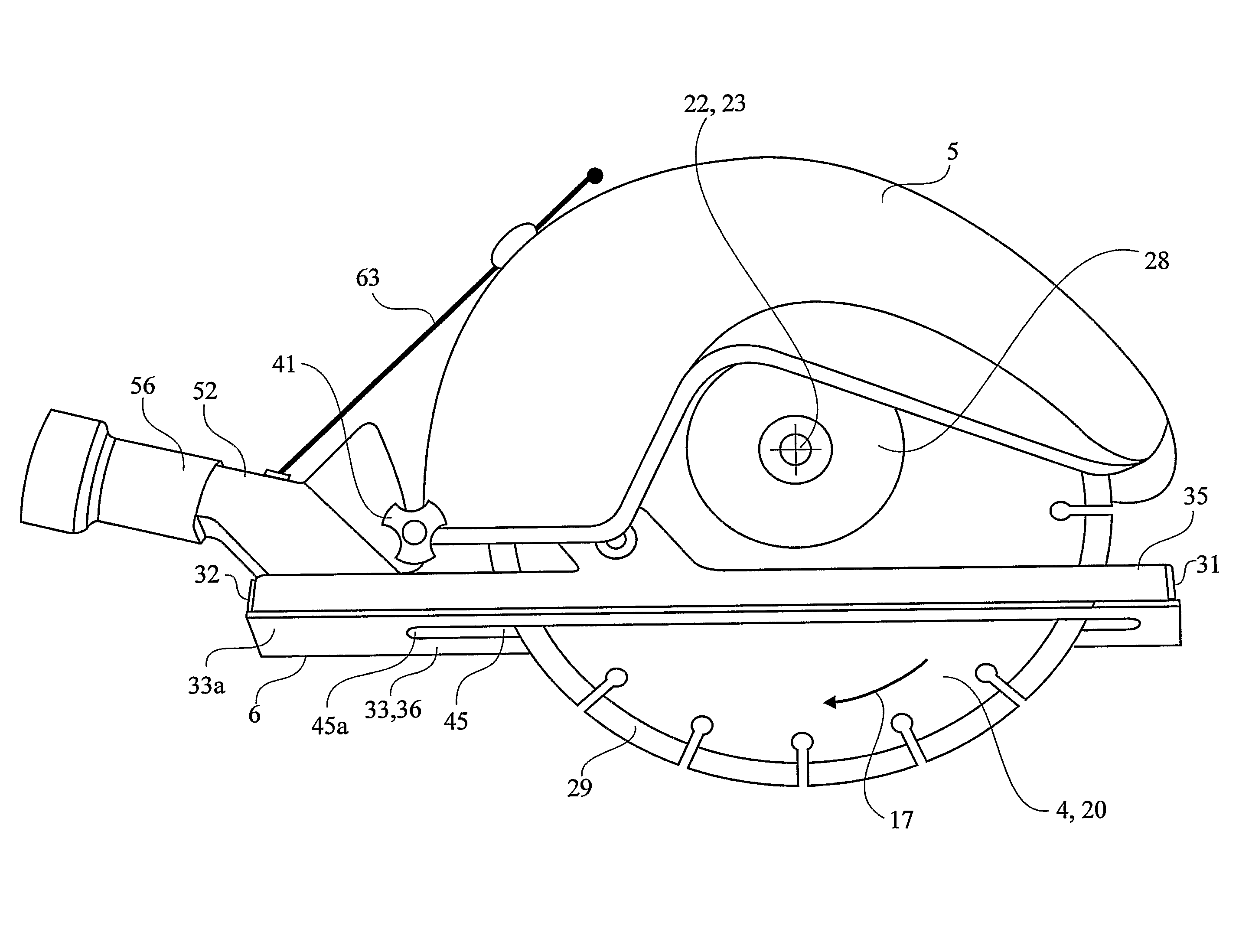
[0007]According to this wide aspect of the invention, the cutting and dust collecting assembly is characterised in that it comprises a rotatable, circular saw blade having a first side, a second side, a peripheral portion defining the working part of the saw blade, and a centre of rotation, that it also comprises a cover device with a terminal member in a rear part of the cover device, that the cover device has a front end, a rear end, a top surface, a bottom surface extending in a plane, and a longitudinal passage for the saw blade, said passage extending through the cover device from its top surface to its bottom surface in a region between the front and rear ends of the cover device, that the saw blade can be moved up and down in said passage, a segment of the saw blade passing through the bottom surface of the cover device, during which movement said centre of rotation, which is positioned above the cover device, is displaced relative to the cover device, that the terminal member includes a terminal chamber having an inlet, the mouth of which coincides with the plane of said bottom surface, and an outlet which can be connected to a vacuum source, and that the direction of rotation of the operating blade is such that the rear part of said segment which has passed beyond the bottom surface of the cover device will move in a direction upwards-rearwards towards the bottom surface, said direction being clock-wise when the saw blade is viewed in a direction towards the first side of the blade. It is also a typical feature that sealing members are provided in said passages, which contact or almost contact the surfaces of the saw blades inside of its peripheral portion so that the flow of air through the passage is significantly reduced.
[0018]Those embodiments, where the sealing body consists of a replacement part, which can be connected with the terminal member, or with a unit consisting of a terminal member and a base plate of metal, respectively, allows a reduction of the total amount of metal in the cover device. This makes the cover device lighter, which is an advantage. It is particularly light if the whole front section is made of a single piece of plastic material, i.e. also including the wing shaped projections which widens the bottom of the cover device. Even if a part of that kind may be somewhat more expensive to manufacture than a smaller and more simple rod, as according to the first mentioned embodiment, where the sealing body is entered into a chamber in the cover device, the cost for such kind of replacement part is still almost negligible in comparison with the cost for a diamond equipped saw blade.
[0020]Still more arrangements can be conceived for preventing air from flowing in sideways to a to high degree under the cover device, particularly in connection with working in objects having very uneven surface, e.g. brick walls, plasted walls, or other surfaces with very coarse surface structure. In such cases, an adhesive sealing strip made of a compressible material may be applied on the wall or corresponding, covering the line along which the kerf shall be made. Suitably, the strip may have a thickness of 10-15 mm and be approximately as wide as the cover device. The material can consist e.g. of foam plastic with an adhesive agent on the underside and possibly a low friction layer on the upper side. If the operator presses the cover device against the strip, at the same time as he moves the assembly forwards, the compressible material will be compressed where details project from the wall and will fill up recesses in the wall, so that the inflow of air because of wall irregularities is reduced or eliminated. One may also conceive to make the sealing strip narrower than the base plate of the cover device and to provide a groove for the sealing strip in the base plate. If said groove has a lower height than the strip, the strip will be compressed in regions of projecting portions on the wall, floor, ceiling or corresponding that shall be worked, in order to provide desired sealing effect in regions between the projecting portions according to above, at the same time as a strip works as a guide for the assembly.
[0022]The joint consists, according to the preferred embodiment, of a hinge, i.e. a joint in which movements take place only in a plane about a shaft. The joint according to the preferred embodiment further comprises a hinge head on one of the two parts which are pivotally connected with one another, i.e. on the blade guard or on the cover device, and a pair of preferably lateral hinge elements provided on the other one of the two parts, one on each side of the hinge head. The shaft extends through the two hinge elements and the hinge head provided between the two hinge elements. The hinge elements provided on each side of the hinge head preferably has the shape of ears, which have flat side surfaces which are pressed against flat side surfaces on the hinge head. All of the said flat surfaces are parallel with one another and with a longitudinal central line of the cover device. Further, the hinge has an axial as well as a radial (diametrical) extension, the length of which in comparison with other dimensions of the assembly are considerable, and that is particularly true as far as the diametrical extension is concerned, which is in the same order, or at the nearest in the same order as the axial extension. The axial extension is preferably at least as long as the width of the sealing body mentioned in the foregoing, or as the width of the box girder which is included in the cover device. The diametrical extension, including the diametrical extension of the flat side surfaces which contact one another, amounts to at least 50% of the axial extension, preferably to at least 75% of the axial extension. The hinge in other words is very robust and is the most important guarantor for maintaining the blade guard fixed sideways in its rear part, where the hinge is positioned. Its significant radial extension at the same time helps preventing the blade guard and hence the saw blade from being obliquely positioned relative to the longitudinal centre line of the cover device after some period of use.
[0024]It is mentioned in the introductory presentation of the background of the invention that it is conventional according to known technique to spray water into the kerf as the kerf is successively established, in order to bind the dust and in that way prevent it from being scattered in the environment. It is also mentioned that the slurry which is formed according to this practice creates a new problem. This is true, but it is also true that access to vacuum cleaner assemblies which could work as a vacuum source for a machine with a cutting and dust collecting assembly based on the principle that the dust shall be removed through vacuum cleaning is not available on many working sites. In some cases it can be necessary or desirable to supply water to the kerf due to authorities' decisions or from other reasons. Also such desired feature can be satisfied by means of the same assembly which according to the invention has been developed for cutting and dust collection. More particularly this is achieved therein that conduits are provided for the supply of water through the sealing body, whether the sealing body is accommodated in a chamber in the cover device or forms a front section of the cover device, which is connected or connectable with the terminal member through a narrow gap between the side surfaces of the saw blade and the side surfaces of the slot which extends through the sealing body. Suitably said conduit mouths in said narrow gaps in a region which, with reference to the longitudinal direction, is positioned in front of the centre of rotation of the saw blade. This contributes to the achievement that water, which is supplied in the narrow gaps, is moved by the saw blade, when the saw blade moves downwards in the kerf, which makes the binding of dust efficient. According to the invention, the dust collection through suction according to the principles of the invention can be combined with the addition of water.

