Marking device

a marking device and marking technology, applied in the field of marking devices, can solve the problems of high operability, defective demolding process, and higher pressure at the border, and achieve the effect of less grooves, sufficient engagement, and reduced size of the marking devi

Active Publication Date: 2011-09-06
URATANISHOJI
View PDF22 Cites 1 Cited by
  • Summary
  • Abstract
  • Description
  • Claims
  • Application Information

AI Technical Summary

Benefits of technology

[0019]Considering the problems described above, one object of the present invention is to provide a marking device having a high operability as well as capability of preventing molten material penetration during a high-temperature molding process.
[0020]The present invention relates to a marking device comprising an outer shell, a rotatable tube and an indicator. The outer shell has an upper surface with an opening and a bottom surface with a threaded hole. The rotatable tube having a cylindrical shape is inserted into the outer shell. The indicator is inserted into the rotatable tube and engages with the threaded hole of the outer shell. When the rotatable tube and the indicator are placed into the outer shell, the upper surfaces of the rotatable tube and the indicator are leveled with that of the outer shell. The surfaces of the outer shell, rotatable tube and the indicator become a part of a wall of a cavity of the molding device to which the marking device is attached. Each of surfaces of the outer shell, the rotatable tube and the indicator includes at least one carved mark. A molten material injected into the cavity of the molding device flows into the carved mark on the upper surface of the outer shell, the rotatable tube and the indicator, and thus the product having a relief on its surface can be obtained.
[0025]As the indicator is rotated for deeper engagement between the threaded portion of the indicator and the threaded hole of the outer shell, the nut moves downwardly and the head of the rotatable tube gradually approaches the inner wall of the outer shell. When the rotatable tube receives the whole head of the indicator, the nut will be apart from the bottom surface of the rotatable tube. When the nut is apart from the bottom surface of the rotatable tube, the upper surfaces of the indicator, rotatable tube and the outer shell are all coplanar. Therefore, there would be no friction between the indicator and the rotatable tube, and between the rotatable tube and the outer shell until the upper surfaces of the indicator, the rotatable tube and the outer surface are leveled with each other. Thus, this configuration minimizes a required torque to be applied to the indicator rotated to assemble the marking device. Further, this configuration comprising a rigid support mechanism (nut) stands relatively higher temperature condition for a longer period than an elastic support mechanism (spring) described below.
[0026]In another embodiment, the support mechanism is a coil spring provided between the bottom of the outer shell and a bottom surface of the rotatable tube. The coil spring elastically pushes up the rotatable tube to prevent the friction between the rotatable tube and the outer shell.
[0030]The present invention includes various embodiments which increases a pressure among the indicator, the rotatable tube and the outer shell.

Problems solved by technology

Thus, the marking device (M) disclosed in Japanese Patent Publication No. 2008-68506 has a high operability, however, it will be lost when used in a high-temperature molding process such as aluminum die cast molding.
A deeper carved arrow (C) may be required to provide a higher torque from the screw driver in order to overcome the high friction between the tapered surfaces, but such deeper mark (C) may result in an arrow relief highly protruded from a surface of the molded product or cause a defective demolding process.
This elastic deformation causes a high stress inside the indicator to be transmitted to the rotational tube and outer shell, which leads to higher pressures at their borders.

Method used


Image

  • Marking device
  • Marking device
  • Marking device

Examples


Embodiment Construction

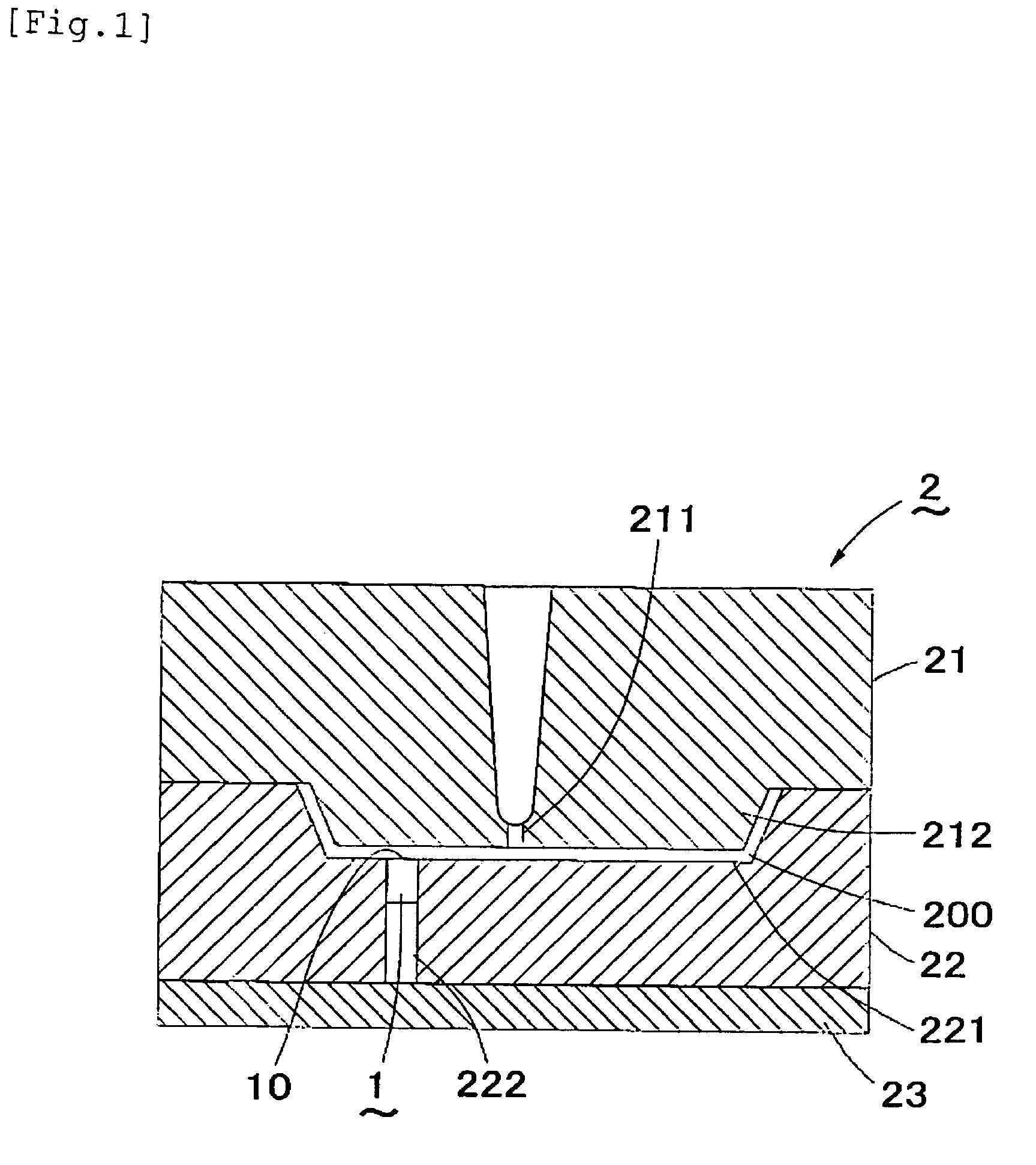
[0060]FIG. 1 shows the marking device of the present invention attached to the molding device.

[0061]The molding device (2) comprises a fixed mold (21), a movable mold (22) approaching or separating from the fixed mold (21), and a movable plate (23) connecting to the movable mold (22) and an actuator (not shown). A force from the actuator is transmitted to the movable mold (22) via the movable plate (23), so that the movable mold (22) can be contact with and apart from the fixed mold (21).

[0062]The fixed mold (21) includes an injection outlet (211) from which a molten material such as a molten metal or a molten resin is injected.

[0063]The fixed mold (21) also includes a protruding part (212) protruding downwardly around the injection outlet (211). The movable mold (22) includes a concave portion (221), in which the protruding part (212) of the fixed mold (21) moves. A volume of the protruding part (212) is smaller than that of the concave portion (221), and the cavity (200) in a pred...


PUM

PropertyMeasurementUnit
coefficient of thermal expansionaaaaaaaaaa
temperatureaaaaaaaaaa
melting pointaaaaaaaaaa

Abstract

A marking device comprises an outer shell in a cylindrical shape with a bottom surface attached to a molding device, a rotatable tube provided inside of the outer shell, an indicator connecting to the bottom of the outer shell and a support mechanism pushing up the rotatable tube from the internal space of the outer shell while the indicator and the outer shell are engaged with each other. The head of the indicator is formed in a frusto-conical shape tapered into the inside of the outer shell. The rotatable tube comprises an inner surface contacting to the outer surface of the head of the indicator, and an outer surface forming a frusto-conical head tapered into the inside of the outer shell from a second carved marks. The outer shell comprises an inner surface contacting to the outer surface of the head of the rotatable tube.

Description

CROSS REFERENCE TO RELATED APPLICATION[0001]This is a continuation-in-part of U.S. patent application Ser. No. 11 / 211,366 (filed on Aug. 24, 2005: U.S. Pat. No. 7,171,894) and U.S. patent application Ser. No. 11 / 644,151 (filed on Dec. 22, 2006 now U.S. Pat. No. 7,503,542).[0002]This application is based upon and claims the benefit of priority from the prior Japanese Patent Application No. 2009-4014 (filed on Jan. 9, 2009), the entire content of which is incorporated herein by reference.BACKGROUND OF THE INVENTION[0003]1. Field of the Invention[0004]This invention relates to a marking device used in marking the surfaces of products during molding process, more specifically, it relates to a marking device having a high operability as well as capability of preventing molten material penetration during high-temperature molding process.[0005]2. Description of the Background Art[0006]Today, various kinds of resin materials or metallic materials are used for molding process thanks to the d...

Claims


Application Information

Patent Timeline
Patent Type & Authority Patents(United States)
IPC IPC(8): B29C33/00B31F1/07
CPCB29C33/424B29C45/374
Inventor URATANI, HIDEKI
Owner URATANISHOJI
Why Eureka
Try Eureka