Method and system for mounting lasers on energy assisted magnetic recording heads

a laser and magnetic recording head technology, applied in the field of laser mounting on energy assisted magnetic recording heads, can solve the problems of time-consuming and easy errors of conventional transducers, adversely affecting the throughput and yield of manufacturing for fabricating conventional eamr disk drives, and affecting the performance of lasers. , the effect of reducing the cost of laser mounting

Active Publication Date: 2011-09-06
WESTERN DIGITAL TECH INC
View PDF2 Cites 200 Cited by
  • Summary
  • Abstract
  • Description
  • Claims
  • Application Information

AI Technical Summary

Problems solved by technology

More specifically, aligning the laser 30 to the desired position with respect to the conventional transducer 28 is time consuming and prone to error.
Further, th...

Method used


Image

  • Method and system for mounting lasers on energy assisted magnetic recording heads
  • Method and system for mounting lasers on energy assisted magnetic recording heads
  • Method and system for mounting lasers on energy assisted magnetic recording heads

Examples


Embodiment Construction

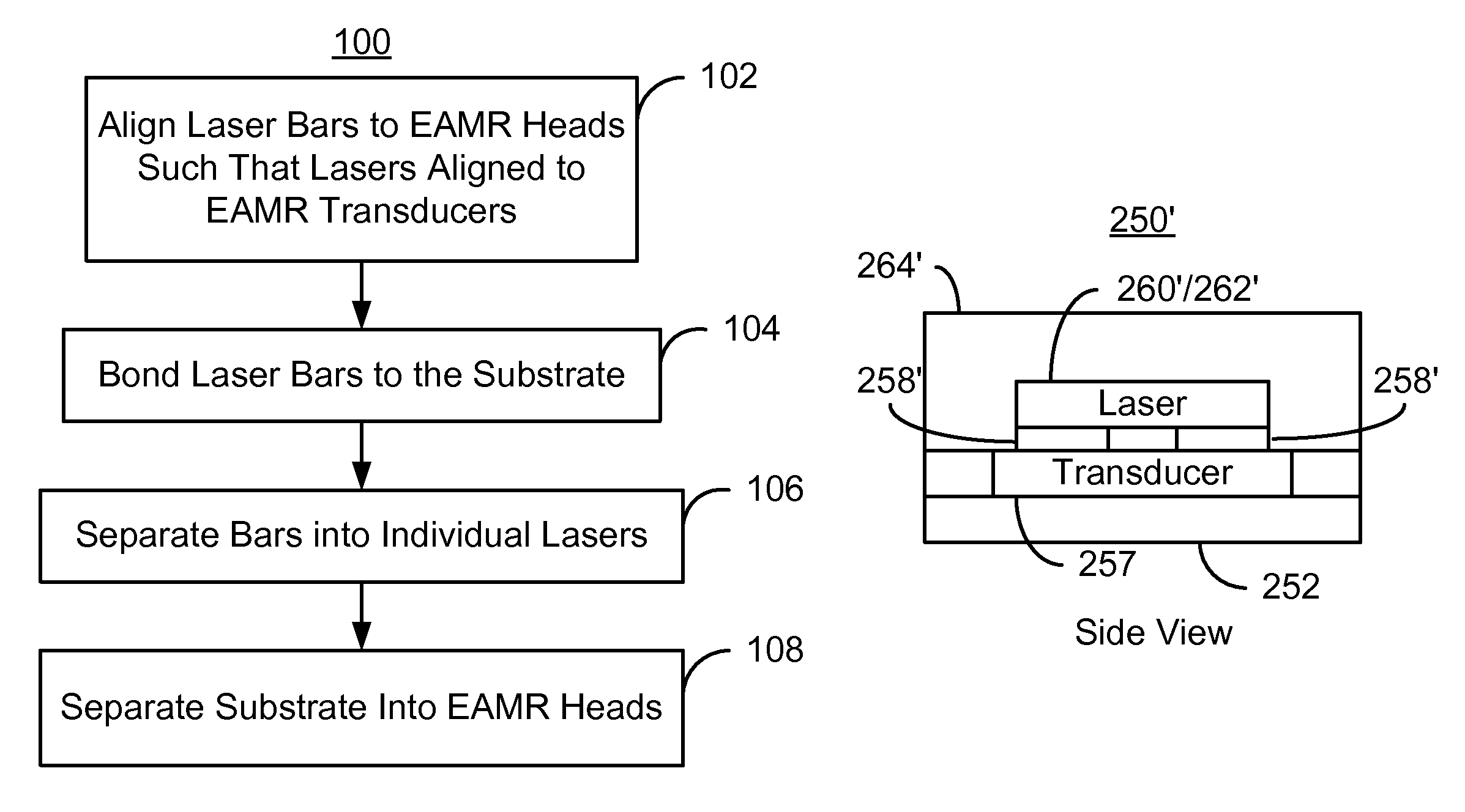
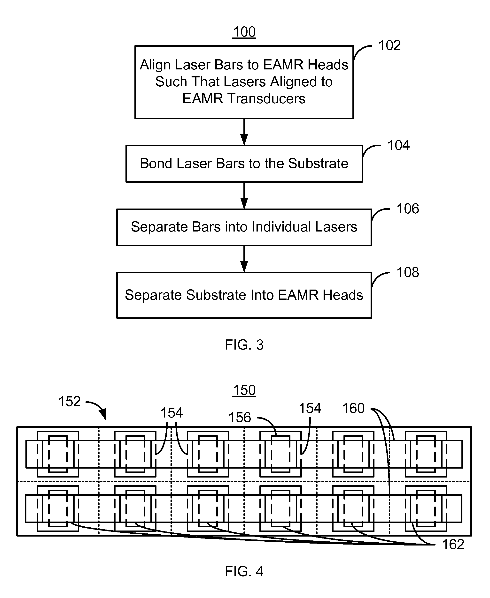
[0014]FIG. 3 is a flow chart depicting an exemplary embodiment of a method 100 for fabricating EAMR heads. Although certain steps are shown, some steps may be omitted, interleaved, performed in another order, and / or combined. The EAMR heads being fabricated may be part of merged heads, each of which includes an EAMR write transducer, a read transducer (not shown) and resides on a slider. Further, the EAMR heads are fabricated on a substrate which, when separated into the individual EAMR heads, corresponds to the slider. The method 100 commences after the EAMR transducers have been fabricated on the substrate.

[0015]Laser bars are aligned to the EAMR heads, via step 102. Each laser bar includes multiple lasers. However, there is no requirement that all of the laser bars have the same number of lasers. The number of lasers in a particular bar may vary and depend upon the specific processing and tolerances used. For example, a laser bar might include five, ten, twenty, forty, fifty, one...


PUM


Abstract

A method and system for providing energy assisted magnetic recording (EAMR) heads including EAMR transducers are described. The method and system include aligning a laser bar to the EAMR heads on a substrate. The laser bar includes lasers in locations corresponding to a portion of the EAMR transducers. The method and system also include bonding the laser bar to the substrate and removing a portion of the laser bar to separate the plurality of lasers. The substrate is separated into the EAMR heads.

Description

BACKGROUND[0001]FIG. 1 depicts a side view of portion of a conventional energy assisted magnetic recording (EAMR) disk drive 10. The conventional EAMR disk drive 10 includes a recording media 12, a conventional slider 20, and a conventional laser diode 30 that are typically attached to a suspension (not shown). The conventional slider 20 has a leading edge 22, a trailing edge 26, and a back side 24. Other components that may be part of the conventional EAMR disk drive 10 are not shown. The conventional slider 20 is typically attached to the suspension at its back side 24. A conventional EAMR transducer 28 is coupled with the slider 20.[0002]The laser diode 30 is coupled in proximity to the EAMR transducer 22 on the trailing edge 26 of the slider 20. Light from the conventional laser diode 30 is provided substantially along the optic axis 32 of the conventional laser diode 30 to the trailing edge 26 of the slider 20. More specifically, light from the laser diode 30 is provided to a g...

Claims


Application Information

Patent Timeline
IPC IPC(8): H01L21/00
CPCB82Y25/00G11B5/314G11B5/3173G11B5/6088G11B2005/001G11B2005/0021
Inventor WANG, LEILEE, SHING
Owner WESTERN DIGITAL TECH INC
Why Eureka
Try Eureka