
Methods for determining in situ the viscosity of heavy oil using nuclear magnetic resonance relaxation time measurements

a technology of nuclear magnetic resonance and in situ measurement, applied in the field of geological formation investigation, can solve the problems of difficult and costly production, failure of high viscosity oil techniques, and poor correlation

Active Publication Date: 2011-09-06
SCHLUMBERGER TECH CORP
View PDF6 Cites 7 Cited by
  • Summary
  • Abstract
  • Description
  • Claims
  • Application Information

AI Technical Summary

Benefits of technology

The invention relates to a method for determining the viscosity of heavy oil samples. The method involves measuring the viscosity of the oil sample at a specific temperature using an NMR experiment. The viscosity is determined based on certain NMR values, such as the logarithmic mean of the measurable T2 distribution. The method can be used in a borehole in a formation to determine the viscosity of the heavy oil sample in real-time. The technical effect of the invention is to provide a reliable and accurate method for determining the viscosity of heavy oil samples, which can be useful in various applications such as oil drilling and production.

Problems solved by technology

Most of the world's oil reservoirs contain heavy and viscous hydrocarbons which are difficult and costly to produce.
However, such techniques fail for highly viscous oils (heavy oils).
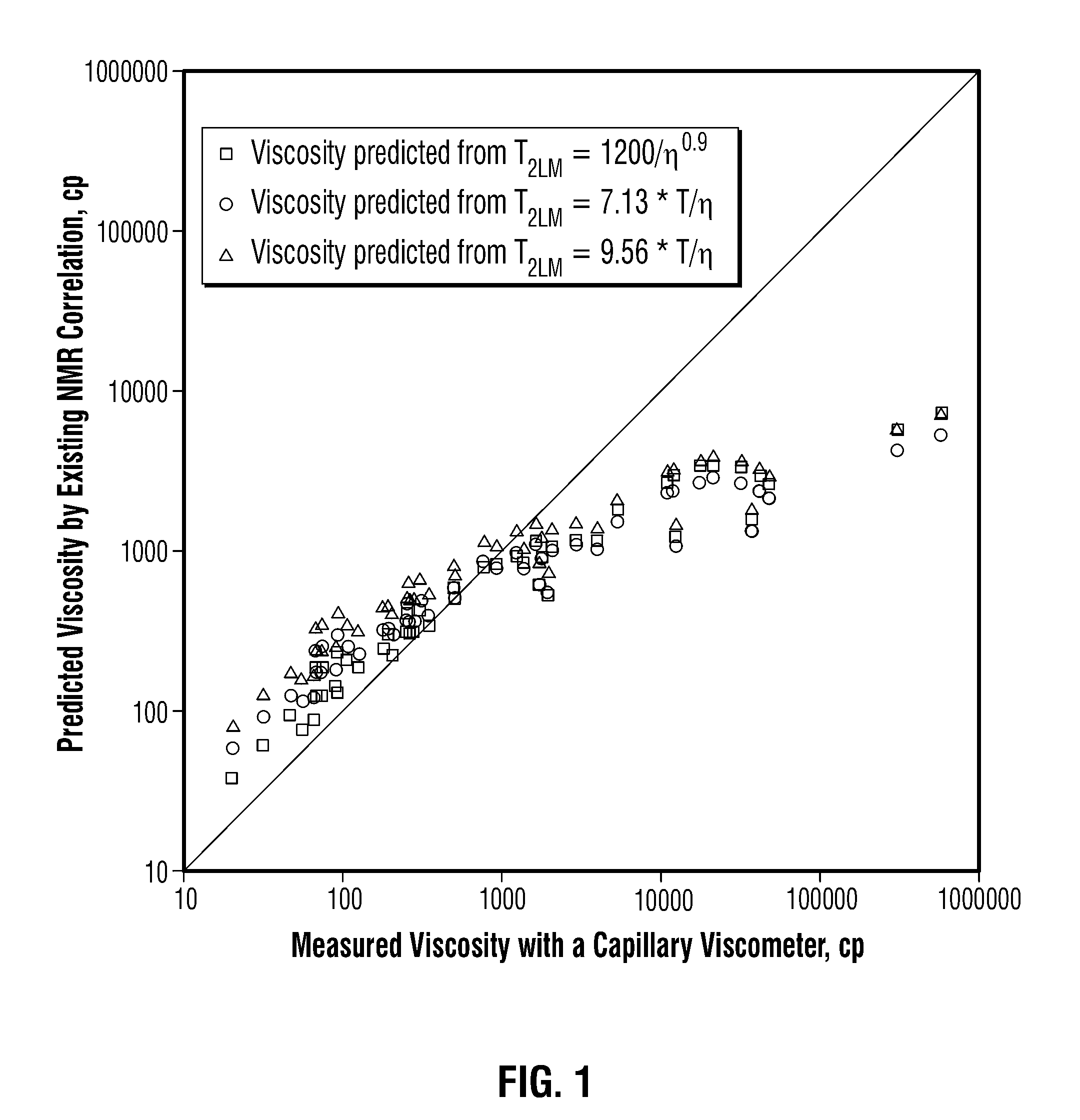
Unfortunately, as can be seen from FIG. 1 which plots the viscosity values measured in a lab (using a capillary viscometer) for heavy oil (HO) samples collected from different locations against the viscosities predicted by the correlations set forth above (using a 2 MHz Maran Ultra NMR instrument available from Oxford Instruments plc of Abingdon, Oxon, United Kingdom), none of the above expressions provided a good correlation.

Method used


Image

  • Methods for determining in situ the viscosity of heavy oil using nuclear magnetic resonance relaxation time measurements
  • Methods for determining in situ the viscosity of heavy oil using nuclear magnetic resonance relaxation time measurements
  • Methods for determining in situ the viscosity of heavy oil using nuclear magnetic resonance relaxation time measurements

Examples


Embodiment Construction

[0021]Before discussing the methods of the invention, a theoretical understanding is useful of how a relationship between viscosity of heavy oil samples and NMR test results can be generated.

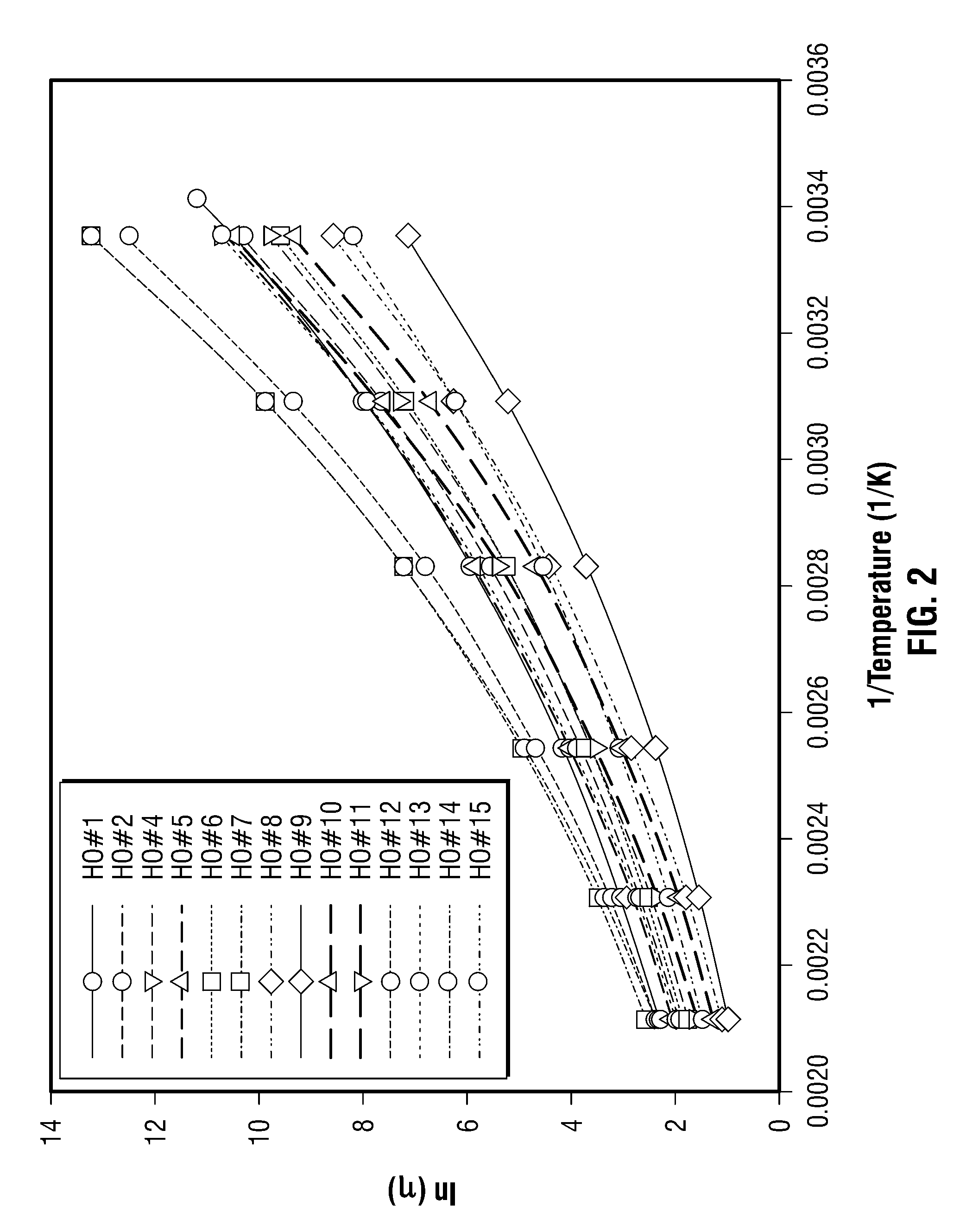
[0022]A starting point for the theoretical understanding does not relate to heavy oils at all, but rather deals with the relationship of viscosity and temperature of simple liquids. The temperature dependence of the viscosity of a liquid is readily observable as the viscosity of the liquid tends to fall (i.e., its fluidity increases) as the temperature of the liquid increases. In the 1890's, Arrhenius showed that there is a logarithmic relationship between viscosity and inverse temperature in many fluids. While this logarithmic relationship well describes certain liquids, it was found that the Arrhenius equations did not describe polymers, such as plastics, which underwent a “glass transition”, a pseudo-second order transition in which melt plastics become rigid on cooling. A model based on free...


PUM


Abstract

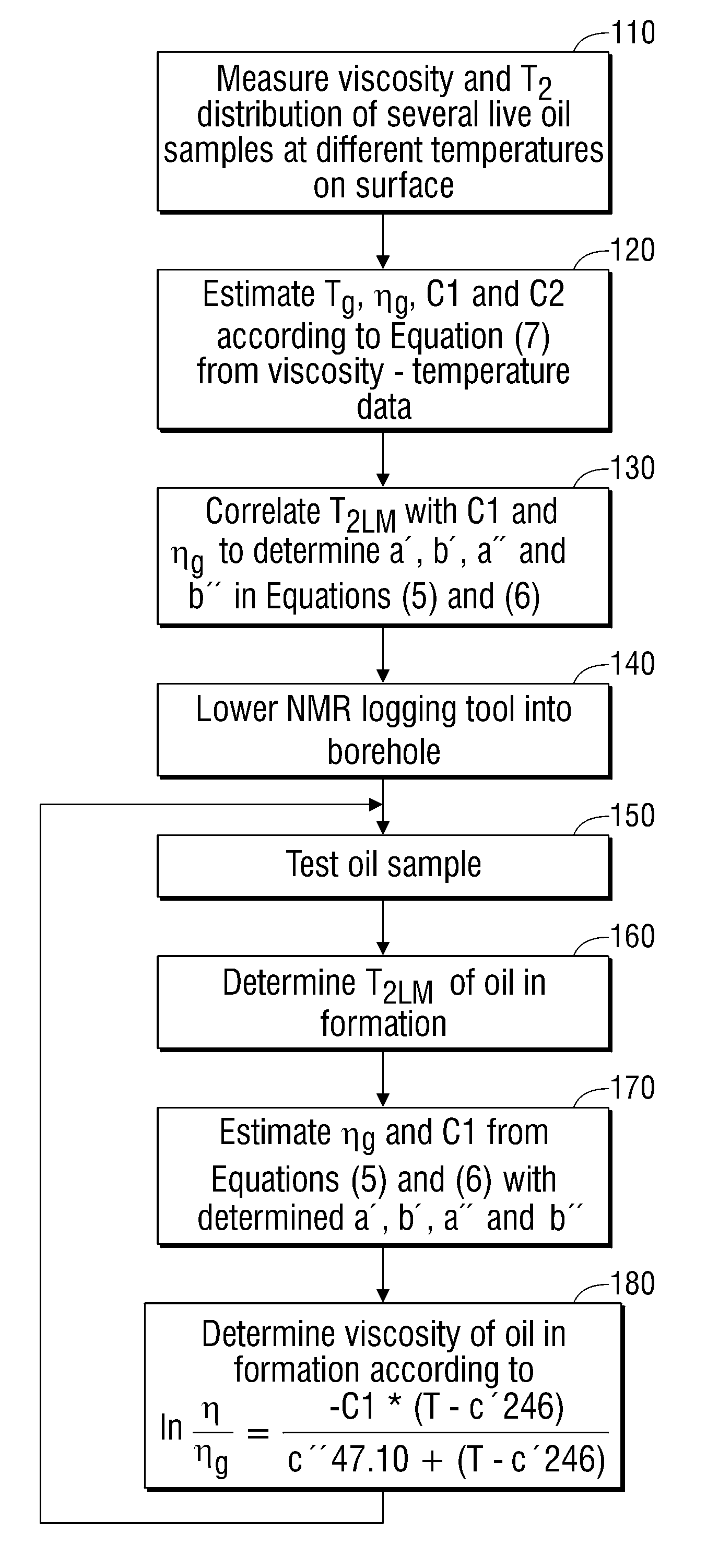
The viscosity η (in centipoise) of a heavy oil sample is determined according to an equation of the form lnηηg=-C⁢⁢1*(T-c′⁢246)c″⁢47.10+(T-c′⁢246),where T is the temperature of the heavy oil, T2LM is the logarithmic mean of the T2 distribution of the sample obtainable from nuclear magnetic resonance (NMR) measurements, c′=1.0±0.05, c″=1.0±0.04, ηg is the glass transition temperature viscosity of the heavy oil and a function of T2LM, and C1 is a variable which is a constant for the heavy oil and is a function of T2LM. Both C1 and ηg are considered functions of certain NMR values associated with the heavy oil sample, with ηg and C1 preferably estimated by empirically fitting data to the equations ln T2LM=a′+b′ ln ηg and ln T2LM=a″+b″C1, where a′, b′, a″ and b″ are constants.

Description

BACKGROUND OF THE INVENTION[0001]1. Field of the Invention[0002]The invention relates broadly to the investigation of geological formations. More particularly, this invention relates to in situ methods of determining the viscosity of heavy oils using nuclear magnetic resonance (NMR) techniques.[0003]2. Description of Related Art[0004]Most of the world's oil reservoirs contain heavy and viscous hydrocarbons which are difficult and costly to produce. Heavy oil viscosity is one of the few criteria available to assess production economics by helping predict if cold production will yield economic production rates, or if thermal processes will be required to reduce the oil viscosity to achieve the required production rates. If cold production is selected, viscosity is again used to help determine whether vertical or horizontal wells should be used. Viscosity data are also used to adjust cold production exploitation strategies if the production rates are significantly lower than expected.[...

Claims


Application Information

Patent Timeline
Patent Type & Authority Patents(United States)
IPC IPC(8): G01V3/00
CPCG01N11/00G01N24/081G01N24/084G01N2015/0061G01N2011/006
Inventor CHENG, YUESHENGKHARRAT, ABDEL M.
Owner SCHLUMBERGER TECH CORP
Learn More