Towing monitor system

a monitor system and towing technology, applied in the field of monitor systems, can solve the problems of reducing the signal or both, the towing monitor system, etc., and achieve the effects of low manufacturing cost, convenient and efficient manufacturing and marketing, and durable, portable and reliable construction

Inactive Publication Date: 2011-09-06
AID JAMES D +2
View PDF3 Cites 38 Cited by
  • Summary
  • Abstract
  • Description
  • Claims
  • Application Information

AI Technical Summary

Benefits of technology

[0031]It is therefore an object of the present invention to provide a new and improved towing monitor system which has all of the advantages of the prior art towing systems of known designs and configurations and none of the disadvantages.
[0032]It is another object of the present invention to provide a new and improved towing monitor system which may be easily and efficiently manufactured and marketed.
[0033]It is further object of the present invention to provide a new and improved towing monitor system which is of durable, portable and reliable constructions.
[0034]An even further object of the present invention is to provide a new and improved towing monitor system which is susceptible of a low cost of manufacture with regard to both materials and labor, and which accordingly is then susceptible of low prices of sale to the consuming public, thereby making such towing monitor system economically available to the buying public.
[0035]Even still another object of the present invention is to provide a towing monitor system for wirelessly determining the status of a trailing vehicle from a leading vehicle and from other locations in a safe, reliable, convenient and economical manner.

Problems solved by technology

When installing the sensing unit in the trailed vehicle, any mounting angle deviation from level would typically create an error, reduction in signal or both.
While these devices fulfill their respective, particular objectives and requirements, the aforementioned patents do not describe a towing monitor system that allows for wirelessly determining the status of a trailing vehicle from a leading vehicle and from other locations in a safe, reliable, convenient and economical manner.

Method used


Image

  • Towing monitor system
  • Towing monitor system
  • Towing monitor system

Examples


Embodiment Construction

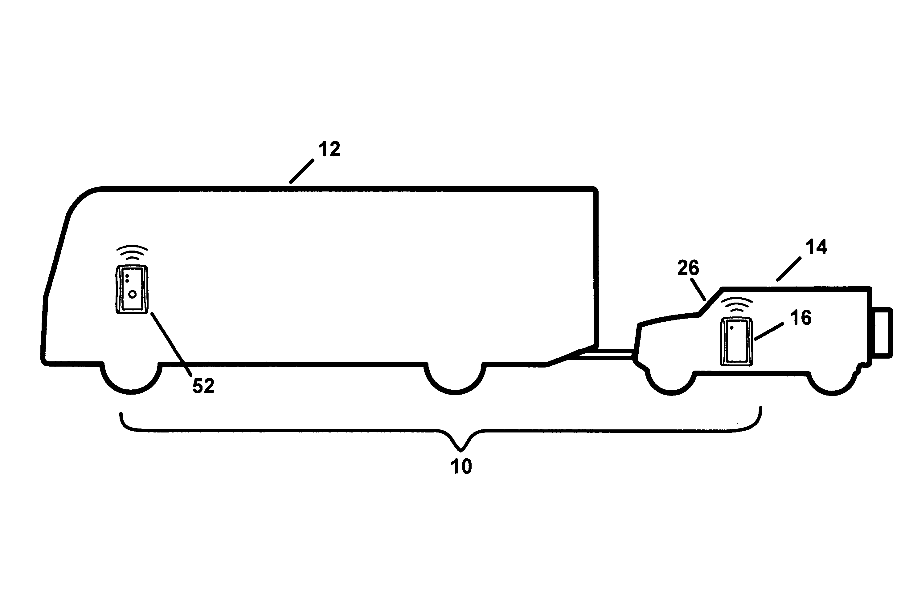
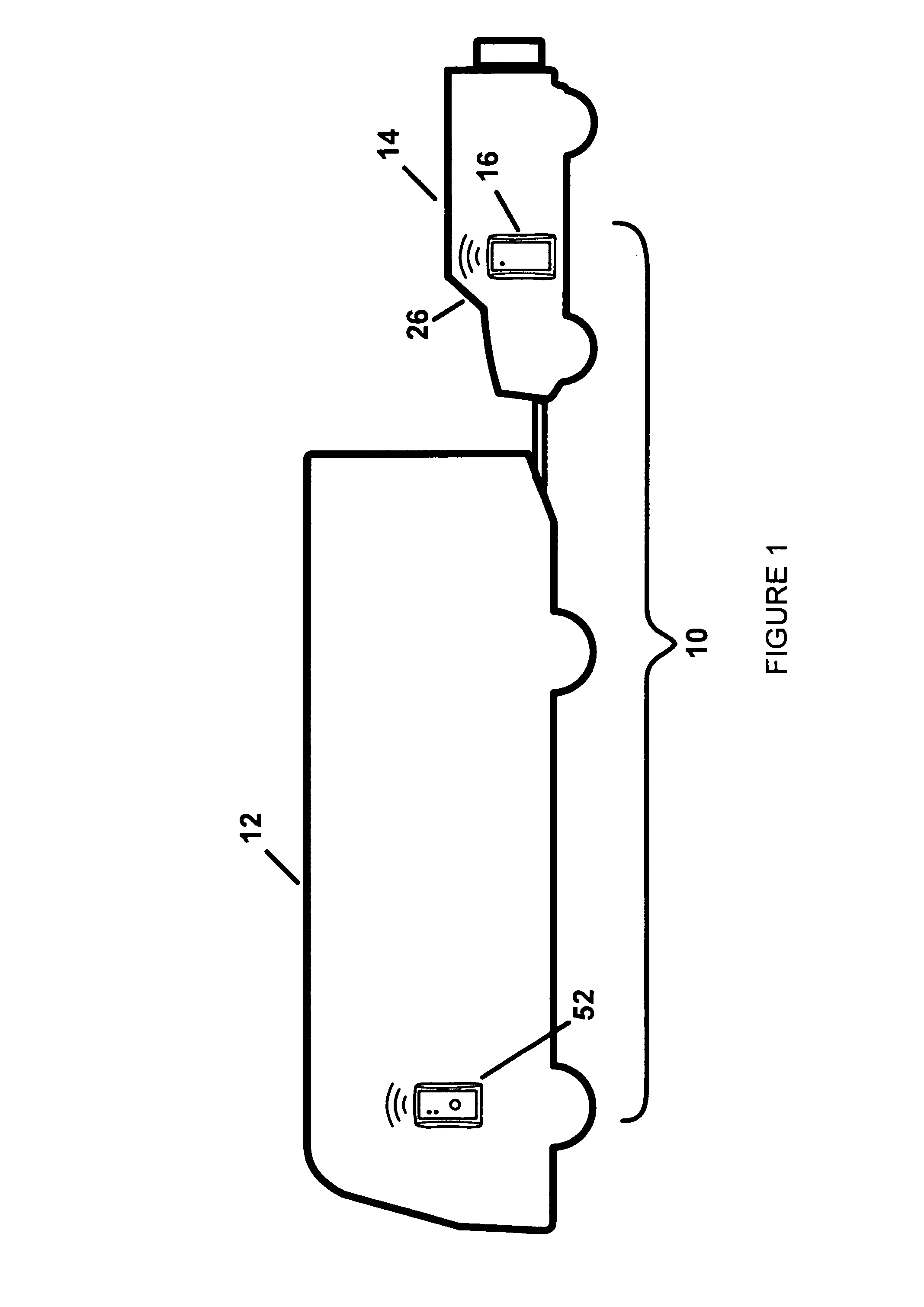
[0048]With reference now to the drawings, and in particular to FIG. 1 thereof, the preferred embodiment of the new and improved towing monitor system embodying the principles and concepts of the present invention and generally designated by the reference numeral 10 will be described.

[0049]The present invention, the towing monitor system 10 is comprised of a plurality of components. Such components in their broadest context include a transmitter unit and a receiver unit. Such components are individually configured and correlated with respect to each other so as to attain the desired objective.

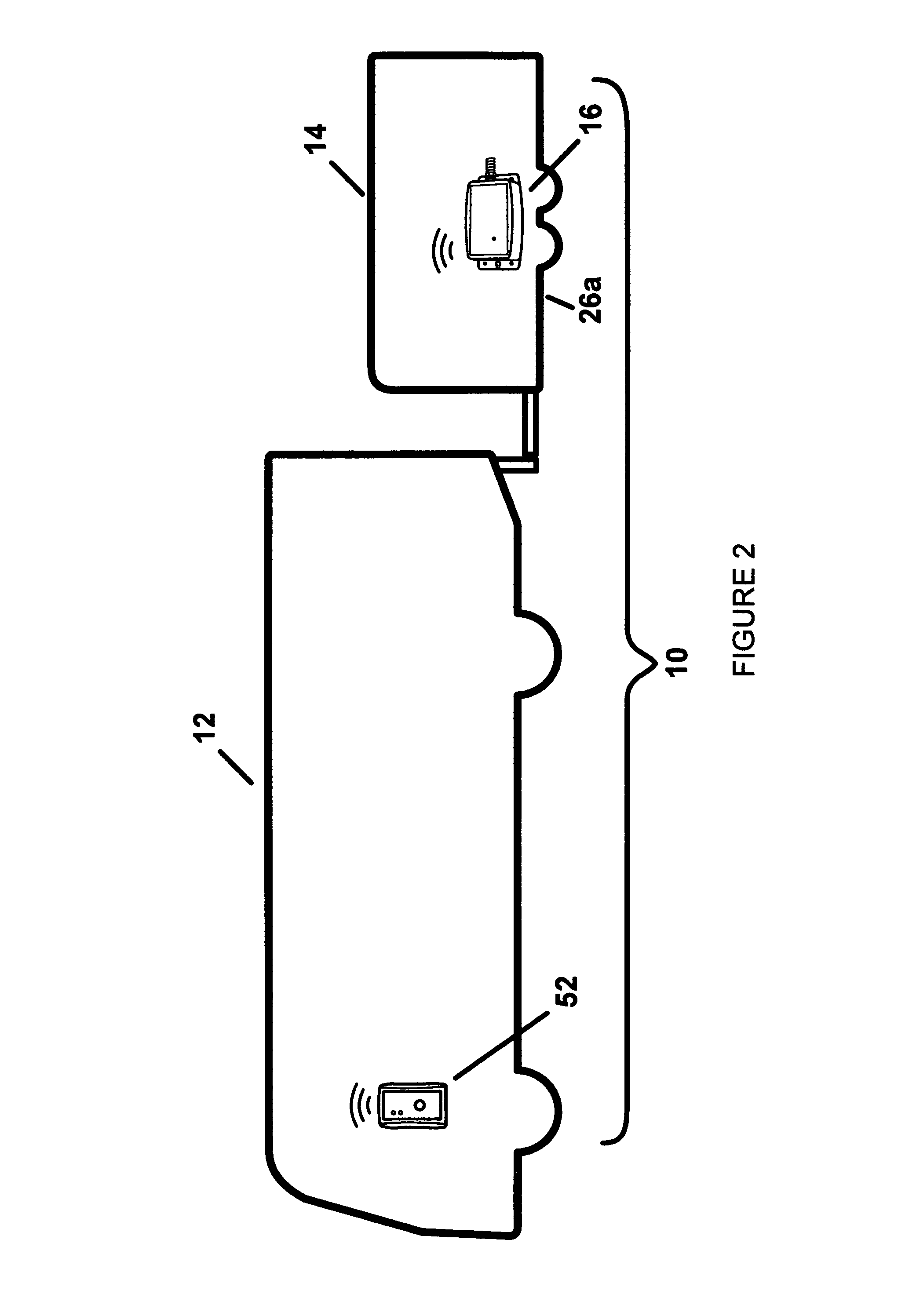
[0050]First provided is a manned self-powered leading vehicle 12. The self-powered leading vehicle is chosen from the class of self-powered leading vehicles. The class of self-powered leading vehicles includes automobiles, recreational vehicles, trucks and the like.

[0051]An unmanned unpowered trailing vehicle 14 is provided. The unpowered trailing vehicle is chosen from the class of unpowered tr...


PUM


Abstract

A transmitter unit has a housing adapted to be coupled in association with a trailing vehicle. The housing also has a multiple axis accelerometer adapted to sense the status of the transmitter unit and a trailing vehicle. The housing also has electronic components coupled with the accelerometer. A receiver unit has a housing adapted to be coupled in association with a leading vehicle. A user in audio proximity to the receiver unit is wirelessly signaled in the event of an anomaly at the transmitter unit.

Description

RELATED APPLICATION[0001]This application is based upon and claims the benefit of Non-Provisional application No. 60 / 923,053 filed Apr. 12, 2007, the subject matter of which is incorporated herein by reference.BACKGROUND OF THE INVENTION[0002]1. Field of the Invention[0003]The present invention relates to a monitor system and more particularly pertains to wirelessly determining the status of a trailing vehicle from a leading vehicle and from other locations in a safe, reliable, convenient and economical manner.[0004]2. Description of the Prior Art[0005]The concept of this device is to monitor the motion of objects. These objects might typically, but not exclusively, be pulled behind a tow vehicle.[0006]The device monitors the object's motion by the use of a single or multi-axis sensor. The signals generated by the sensor are then processed through algorithms, real time or otherwise, to detect specific malfunctions, parameters or deviations from normal operation. These algorithms may...

Claims


Application Information

Patent Timeline
Patent Type & Authority Patents(United States)
IPC IPC(8): G08G1/00
CPCB60D1/30B60D1/58
Inventor AID, JAMES D.CAMERON, NORMAN F.DIN, SHAHID Q.
Owner AID JAMES D
Why Eureka
Try Eureka