
Liquid crystal display and driving method thereof

a technology of liquid crystal display and driving method, which is applied in the direction of non-linear optics, static indicating devices, instruments, etc., can solve the problems of human eyes feeling uncomfortable and the uniformity of impulse-type backlight modules

Active Publication Date: 2011-09-06
AU OPTRONICS CORP
View PDF16 Cites 9 Cited by
  • Summary
  • Abstract
  • Description
  • Claims
  • Application Information

AI Technical Summary

Benefits of technology

[0015]It is therefore an object of the invention to provide a liquid crystal display of improving the frame flicker phenomenon, and a driving method thereof, wherein a dimming frequency of a dimming control signal is a multiple of a frame rate such that the frame flicker phenomenon is eliminated.
[0018]In the liquid crystal display and the driving method thereof, a dimming frequency of the dimming control signal is configured to be a multiple of the frame rate and the dimming control signal is delayed by a period of delay time and then outputted to the backlight module driving circuit. Thus, the frame flicker phenomenon of the liquid crystal display is eliminated, the phenomenon of slow movement of the horizontal black band is improved, and the frame quality of the liquid crystal display is enhanced.

Problems solved by technology

Because the current liquid crystal display is developed toward the trend of large-scale specification, the uniformity of the impulse type backlight module deteriorates due to the leakage current if the impulse type backlight module adopts the analog dimming method.
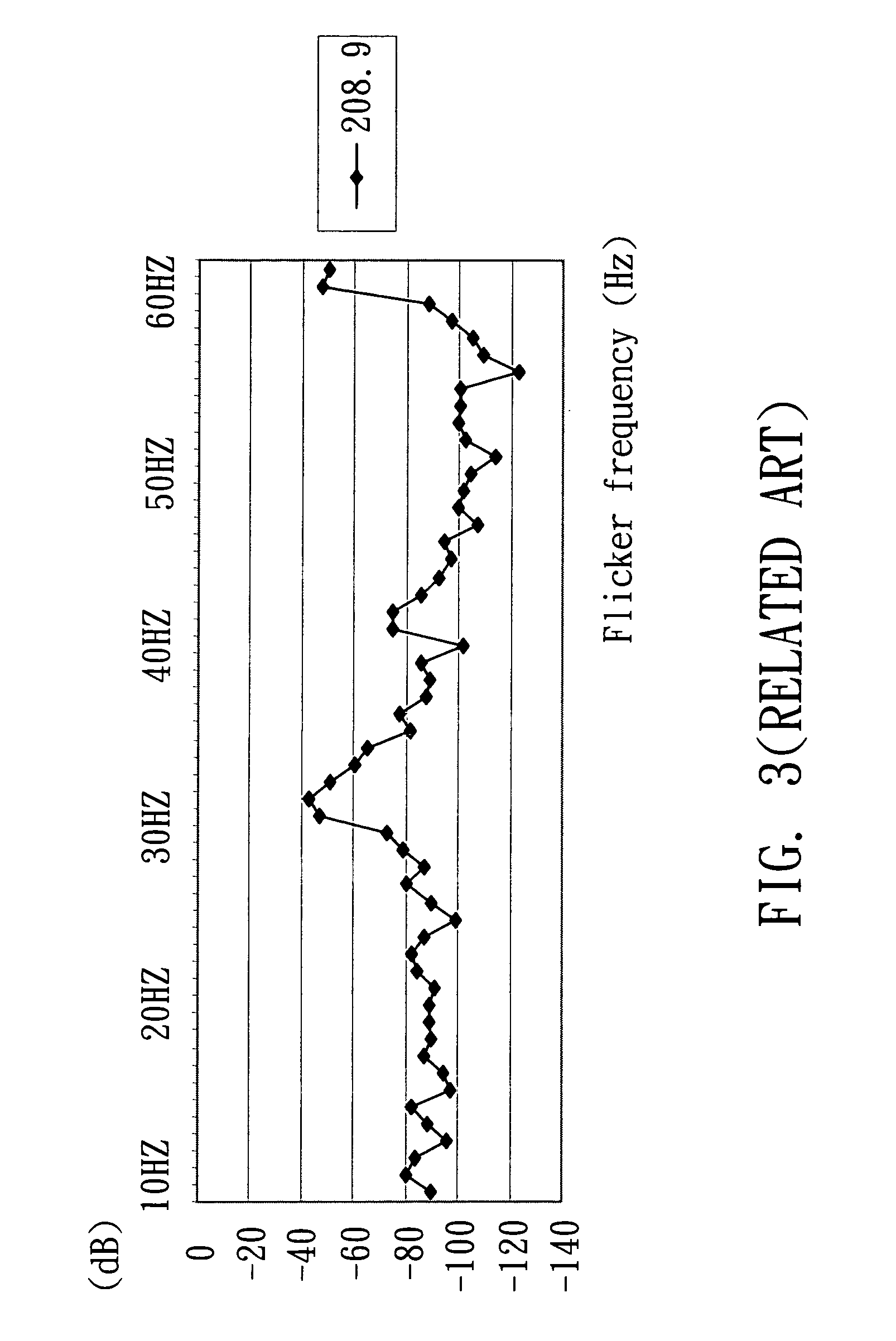
When the dimming frequency interacts with the frame rate to form a new flicker frequency falling within the range that can be sensed by the human eyes, the frame flicker phenomenon is formed on the liquid crystal display panel, and the human eyes may feel uncomfortable.

Method used


Image

  • Liquid crystal display and driving method thereof
  • Liquid crystal display and driving method thereof
  • Liquid crystal display and driving method thereof

Examples


Embodiment Construction

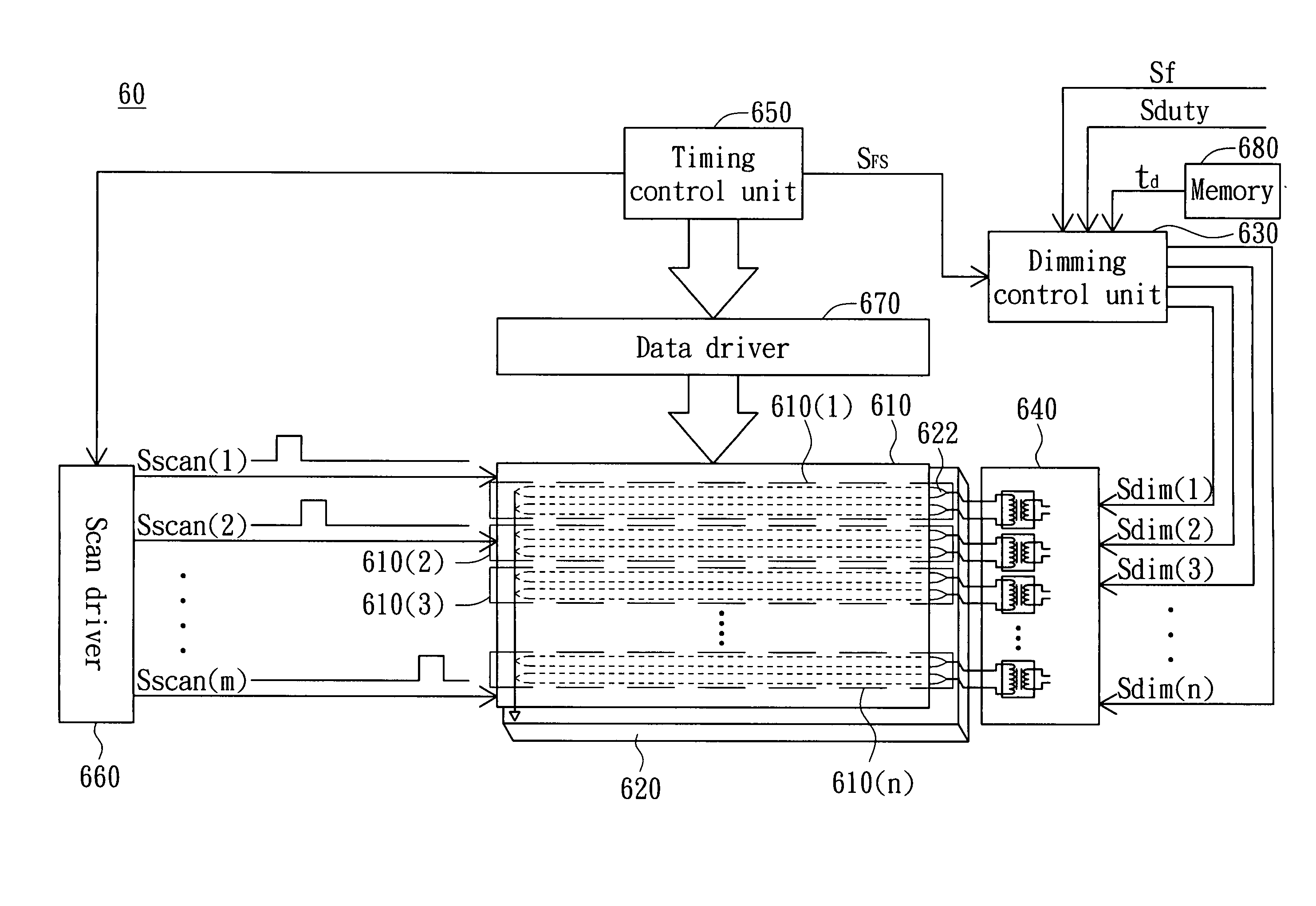
[0029]FIG. 6 is a block diagram showing a liquid crystal display 60 according to a preferred embodiment of the invention. Referring to FIG. 6, the liquid crystal display 60 includes a liquid crystal display panel 610, a backlight module 620, a dimming control unit 630 and a backlight module driving circuit 640.

[0030]The liquid crystal display panel 610 has multiple horizontal display areas, such as the horizontal display areas 610(1) to 610(n), and each horizontal display area has multiple pixels.

[0031]The backlight module 620 includes a plurality of lighting devices 622 respectively corresponding to the pixels in the horizontal display areas 610(1) to 610(n), wherein “n” is a positive integer. For example, the backlight module 620 may be an impulse type backlight module, and the lighting device 622 may be a lighting source such as a cold cathode fluorescent lamp (CCFL), a light emitting diode (LED) or a plasma display.

[0032]The dimming control unit 630 generates dimming control sig...


PUM


Abstract

A liquid crystal display and a driving method thereof. The liquid crystal display includes a liquid crystal display panel, a backlight module, a dimming control unit and a backlight module driving circuit. The liquid crystal display panel has a first display area and a second display area. The backlight module includes a plurality of lighting devices respectively corresponding to pixels in the first display area and the second display area. The dimming control unit generates at least one dimming control signal having a dimming frequency which is a multiple of a frame rate of the liquid crystal display panel. The backlight module driving circuit periodically drives the lighting devices in sequence according to the dimming control signal.

Description

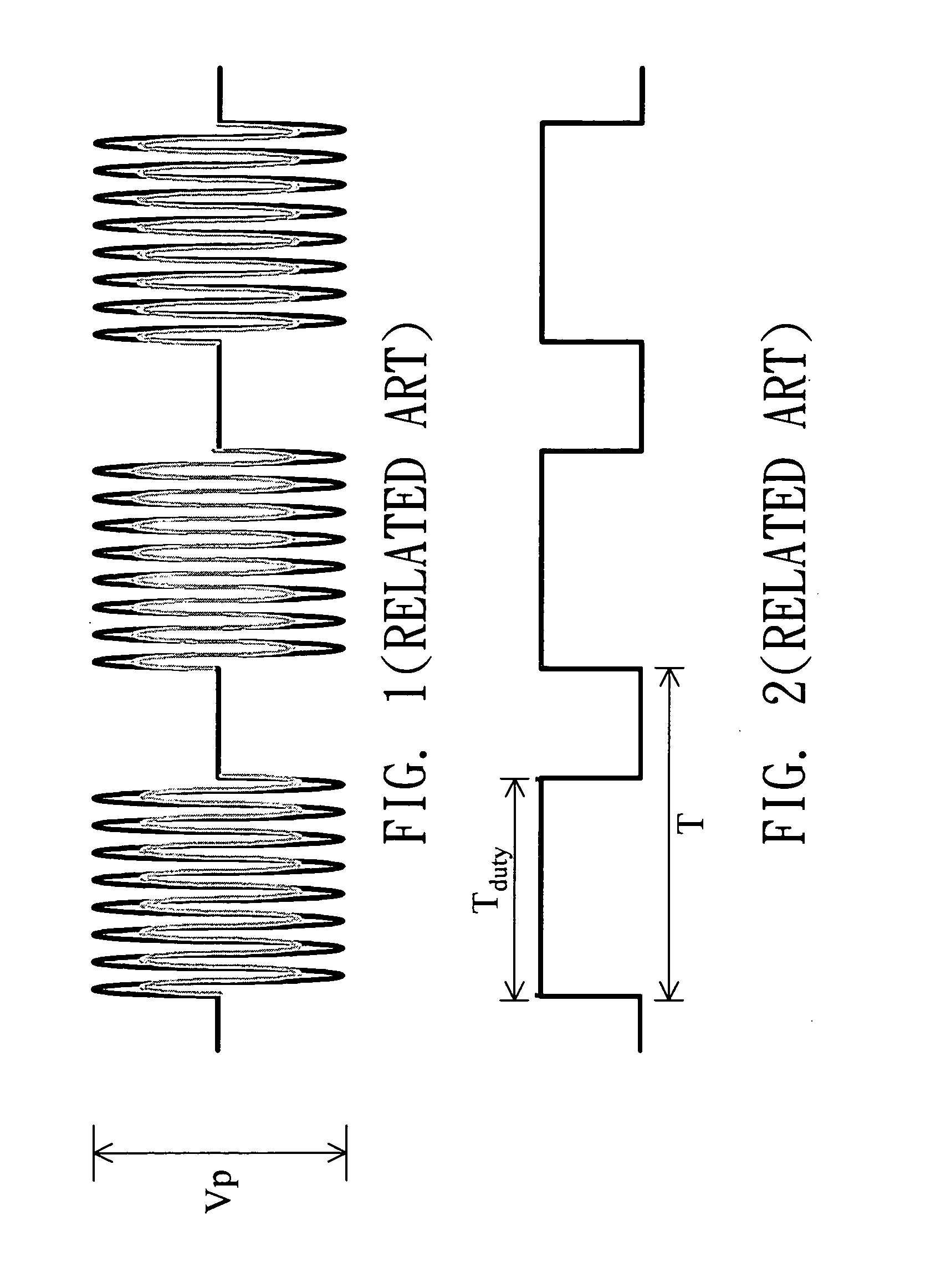
[0001]This application claims the benefit of Taiwan application Serial No. 95103589, filed Jan. 27, 2006, the subject matter of which is incorporated herein by reference.BACKGROUND OF THE INVENTION[0002]1. Field of the Invention[0003]The invention relates in general to a liquid crystal display and a driving method thereof, and more particularly to a liquid crystal display of improving a frame flicker phenomenon, and a driving method thereof.[0004]2. Description of the Related Art[0005]In order to make the liquid crystal display possess a better image quality, a backlight module for controlling on and off of a lighting device to reduce the frame retained image and enhance the motion picture quality has been disclosed.[0006]The dimming methods for the backlight module may be divided into an analog dimming method and a burst dimming method.[0007]FIG. 1 shows a waveform of an output voltage for changing the luminance of a lamp by way of analog dimming. The analog dimming utilizes a cont...

Claims


Application Information

Patent Timeline
Patent Type & Authority Patents(United States)
IPC IPC(8): G09G3/36
CPCG09G3/342G09G3/3611G09G2320/0247G09G2320/064
Inventor HSU, CHIH-CHELYU, LI-RU
Owner AU OPTRONICS CORP
Learn More