Spatial filter in sample investigation system

Inactive Publication Date: 2011-09-06
J A WOOLLAM CO
View PDF30 Cites 2 Cited by
  • Summary
  • Abstract
  • Description
  • Claims
  • Application Information

AI Technical Summary

Benefits of technology

[0083]Finally, it is noted that the purpose of present invention is to selectively attenuate and reduce the presence of secondary maxima falling outside a measurement s

Problems solved by technology

Instead, it often presents irregularly as a function of radius, (eg. easily visualized as being generally similar to the Fourier transform of a square wave), and such irregular intensity content can adversely affect e

Method used


Image

  • Spatial filter in sample investigation system
  • Spatial filter in sample investigation system
  • Spatial filter in sample investigation system

Examples


Example

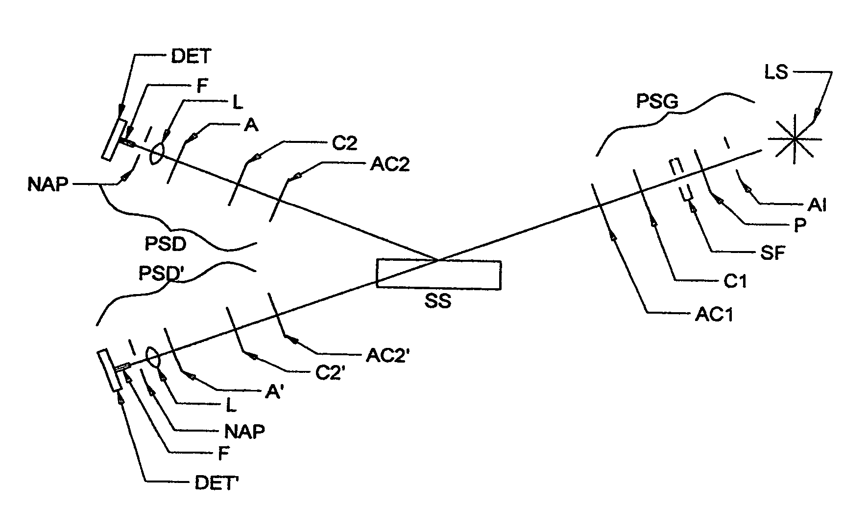
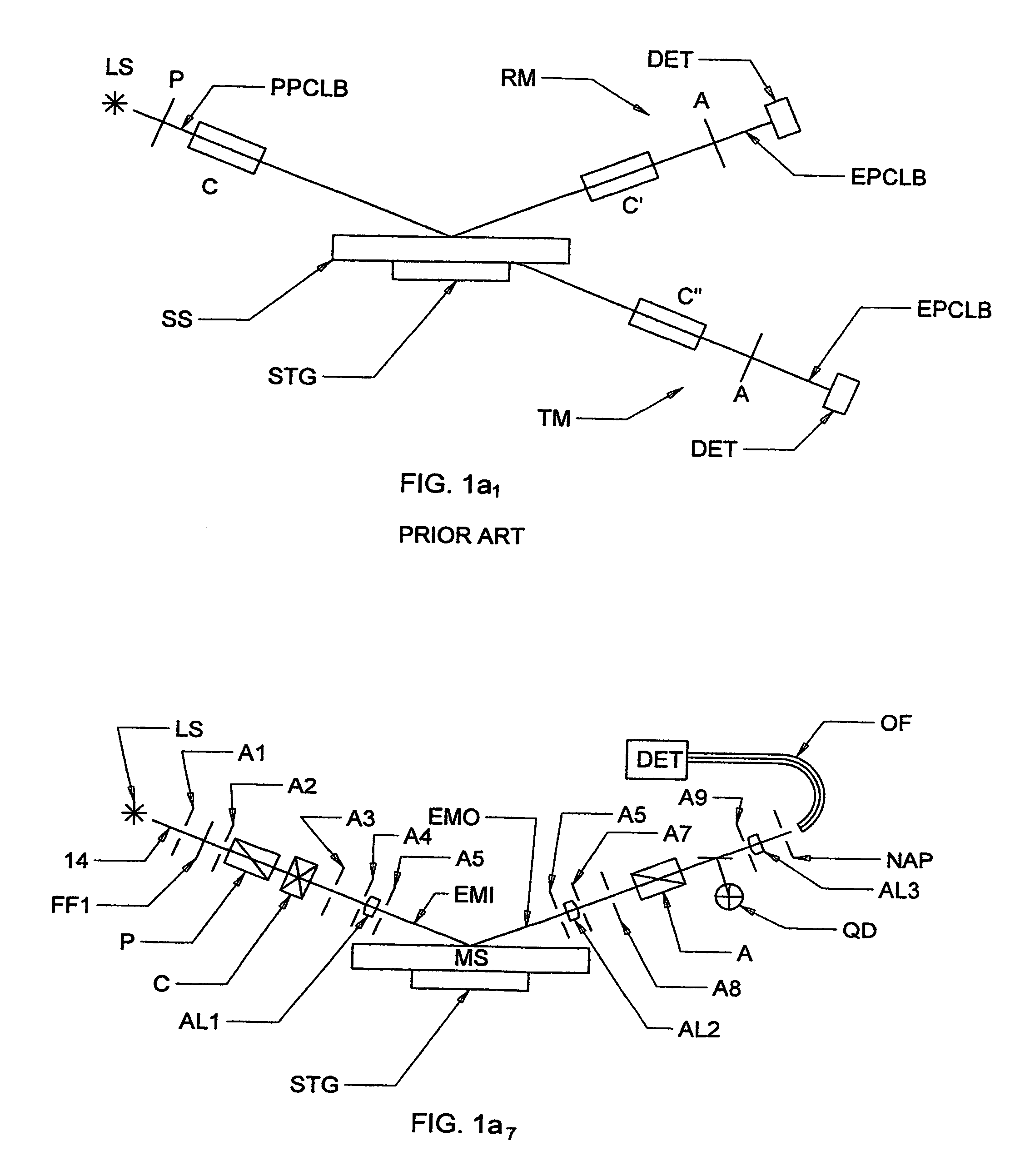
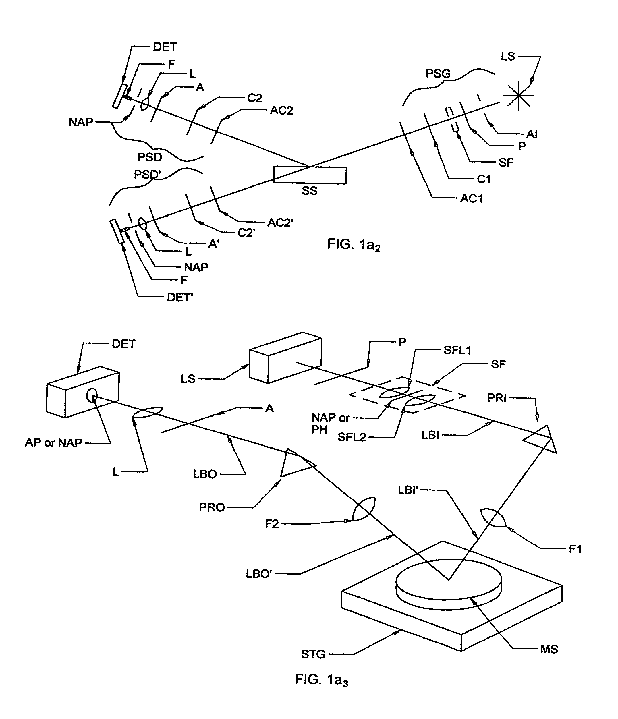
[0100]Turning now to the Drawings, there is shown in FIG. 1a1 a demonstrative Ellipsometer system as disclosed in U.S. Pat. No. 5,872,630, demonstrating both reflection and transmission modes, and comprising a Source of Electromagnetic Radiation (LS), a Polarizer (P), Compensator(s) (C) (C′) (C″), and a Detector (DET). Source (LS) is shown to provide a beam of electromagnetic radiation (PPCLB), and a beam of electromagnetic radiation (EPCLB) is shown reflecting from / transmitting through a Sample System (SS). FIG. 1a6 shows the integrated spatial filter system added to the system of FIG. 1a1. Note the distinguishing Aperture (AI), Focusing Means (L), Aperture (NAP) and Optical Fiber (F) of the present invention present in FIG. 1a6. In use Aperture (AI), is imaged by Focusing Means (L) to Aperture (NAP). The effect of Aperture (AI), Focusing Means (L), Aperture (NAP), and the Optical Fiber (F) is to eliminate an outer annulus of a beam focused on an end of the Optical Fiber (F), by sa...


PUM


Abstract

Systems which utilize electromagnetic radiation to investigate samples and include at least one spatial filter which has an aperture having an opening therethrough of an arbitrary shape, including methodology for fabracting the aperture on an end of an optical fiber per se.

Description

[0001]This Application is a CIP of application Ser. No. Ser. No. 11 / 648,060 Filed Dec. 29, 2006 now U.S. Pat. No. 7,544,622 and therevia of 11 / 204,929 Filed Aug. 15, 2005 now U.S. Pat. No. 7,468,794, and therevia is a CIP of application Ser. No. 10 / 178,723 Filed Jun. 24, 2002, (now U.S. Pat. No. 6,950,182); and is also a CIP from application Ser. No. 10 / 699,540 Filed Nov. 1, 2003 (now U.S. Pat. No. 7,158,231).TECHNICAL FIELD[0002]The present invention relates to systems which utilize electromagnetic radiation to investigate samples, and more particularly to systems which utilize electromagnetic radiation to investigate samples which comprise at least one spatial filter having an aperture with an opening therein of an arbitrary shape.BACKGROUND[0003]Not limited to, but particularly in the case where an electromagnetic beam is utilized to investigate a sample system which presents with a varying depth surface topology, it is important to provide an electromagnetic beam of a known late...

Claims


Application Information

Patent Timeline
IPC IPC(8): G01J4/00
CPCG01J1/02G01J1/0295G01J1/04G01J1/0425G01J1/0437G01J1/0451G01J1/0462G01N21/211G01N21/55G02B27/46
Inventor LIPHARDT, MARTIN M.HE, PINGJOHS, BLAINE D.HERZINGER, CRAIG M.
Owner J A WOOLLAM CO
Why Eureka
Try Eureka