Method for suppressing vibration and device therefor

a technology of vibration suppression and device, which is applied in the direction of vibration measurement in solids, fluid pressure measurement by mechanical elements, machine part testing, etc., can solve the problems of hardly acquiring accurate optimal rotation speed, high technique for using this device, and inability to accurately suppress “chatter vibration” , to achieve optimal rotation speed, optimal rotation speed, the effect of optimal rotation speed

Inactive Publication Date: 2011-09-06
OKUMA CORP
View PDF19 Cites 12 Cited by
  • Summary
  • Abstract
  • Description
  • Claims
  • Application Information

AI Technical Summary

Benefits of technology

[0011]An object of the present invention is to provide a vibration suppressing device capable of acquiring an optimal rotation speed by which chatter vibration can be effectively suppressed.
[0012]Another object of the present invention is to provide a vibration suppressing method and a device therefor, which can acquire an accurate and stable rotation speed for suppressing vibration without consecutively decreasing or consecutively increasing of the rotation speed even when chatter is generated intermittently.
[0019]According to the present invention, a more exact optimal rotation speed can be immediately calculated, since a “chatter vibration” generated at the actual rotation of a rotary shaft is detected to calculate an optimal rotation speed. Therefore, an amplification of a “chatter vibration” can be accurately suppressed, and thus a chatter mark is not remained on the machined face.
[0020]Further, whenever a frequency-domain vibration exceeds a predetermined threshold value, the vibration, the frequency of chatter vibration, and the rotation speed of the rotary shaft are stored in store unit as machining information. When a vibration exceeds the threshold value after the information is stored, the optimal rotation speed is calculated by using previous machining information stored in the store unit. Therefore, an optimal rotation speed at which a regenerative chatter vibration is least generated, indicated in a predicted stability chart, can be easily calculated. Thus, finishing of workpiece surface roughness can be kept in a high level.
[0021]Furthermore, according to the present invention, the machining information is stored and a stable rotation speed is calculated by which chatter vibration of a rotary shaft can be suppressed based on the previous machining information. Therefore, the calculated stable rotation speed is not greatly different from the previous stable rotation speed. Thus, even when chattering is generated intermittently, consecutively decreasing or consecutively increasing of the rotation speed can be prevented.

Problems solved by technology

The method for suppressing vibration disclosed in Patent document 1 requires an expensive impulse device, and a high technique for using this device, which takes time and effort.
Further, since a characteristic frequency measured before machining does not correspond with a characteristic frequency during the machining, an accurate optimal rotation speed is hardly acquired.

Method used


Image

  • Method for suppressing vibration and device therefor
  • Method for suppressing vibration and device therefor
  • Method for suppressing vibration and device therefor

Examples


first embodiment

[0030]A vibration suppressing device according to one preferred embodiment of the present invention will be described below referring to the drawings.

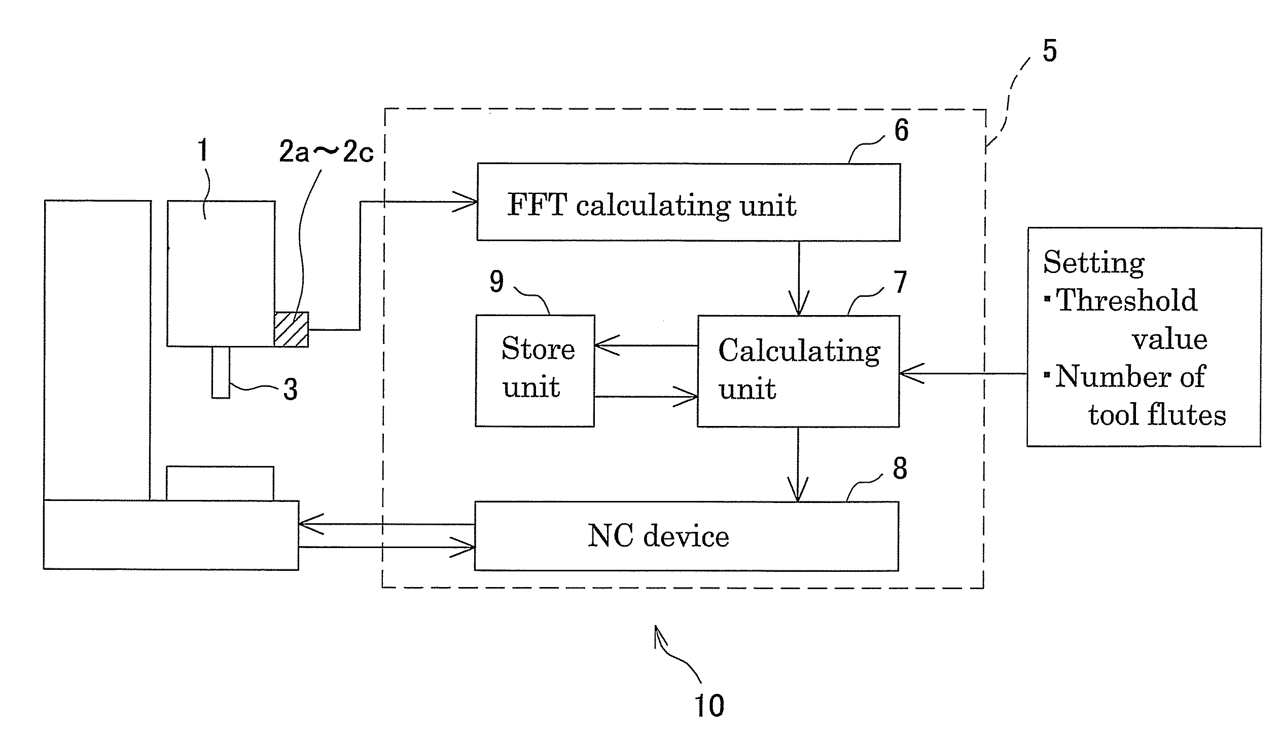
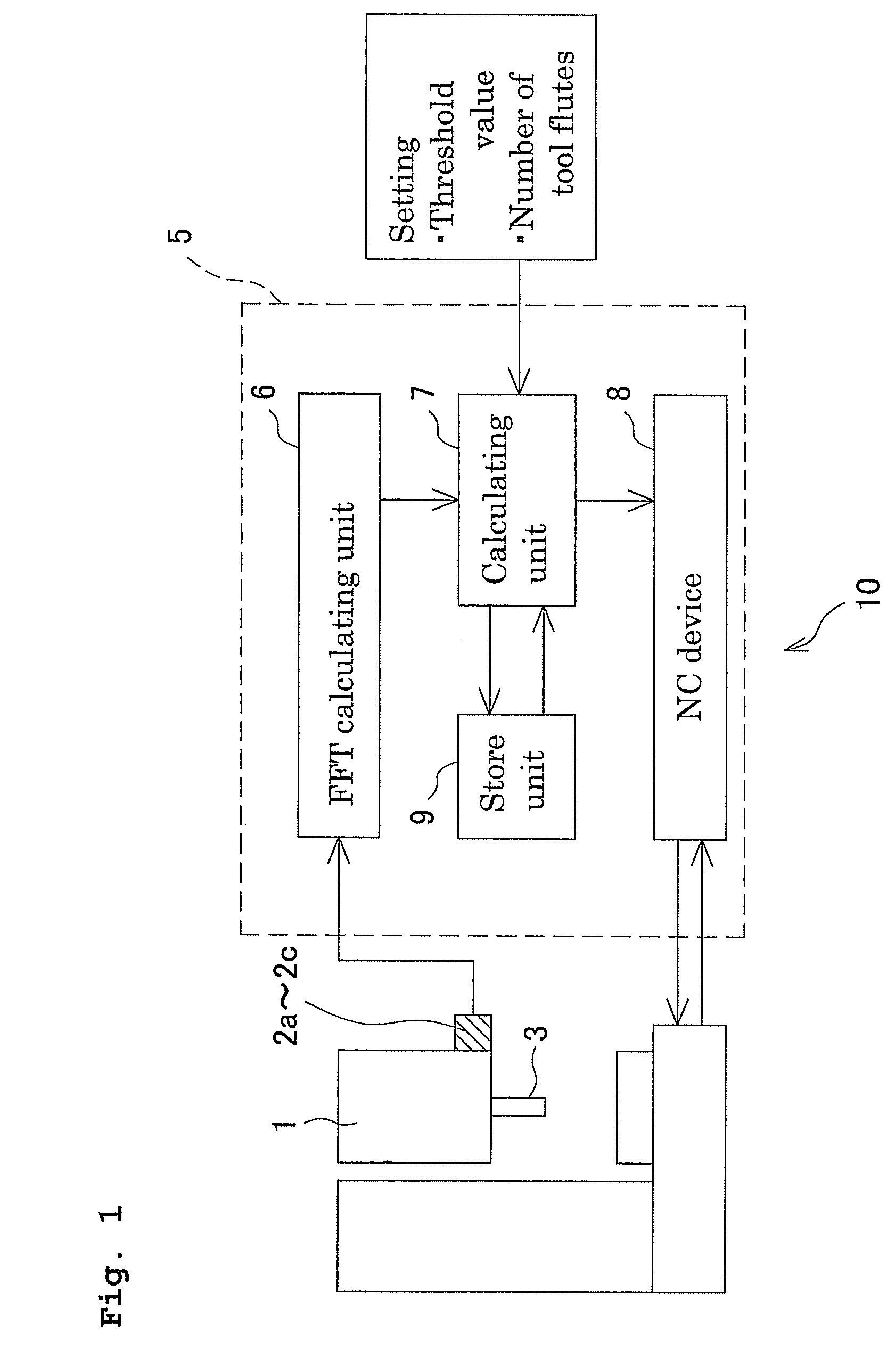
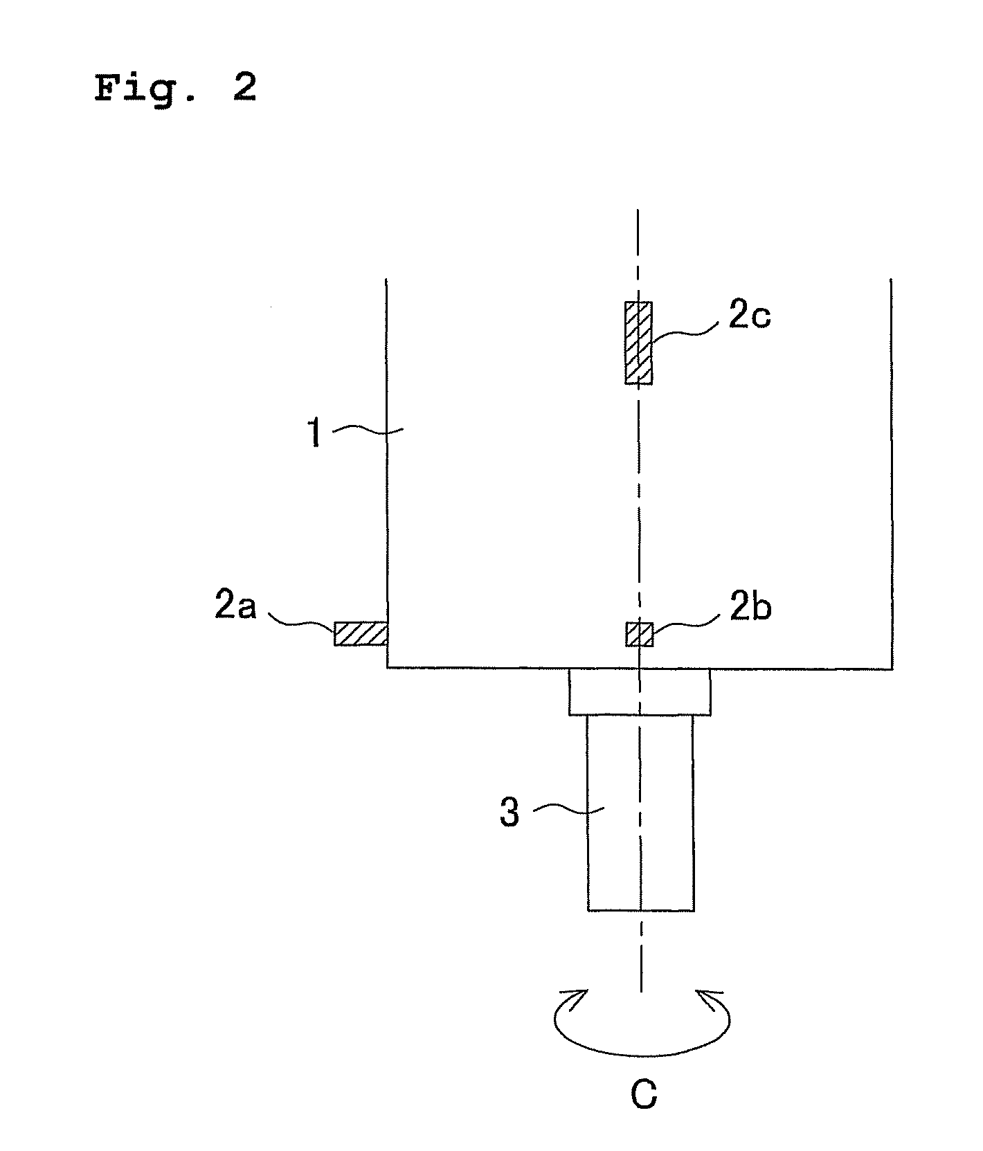
[0031]FIG. 1 is a view to illustrate a block diagram of a vibration suppressing device 10. FIG. 2 is a side face view of a rotary shaft housing 1 as an object of vibration suppressing. FIG. 3 is a view to illustrate a rotary shaft housing 1 from an axial direction.

[0032]The vibration suppressing device 10 is a device for suppressing a “chatter vibration” generated at a rotary shaft 3 which is provided at the rotary shaft housing 1 so as to be rotatable around a spindle C. The vibration suppressing device 10 includes vibration sensors (detection unit) 2a to 2c for detecting a time-domain vibrational acceleration (which means vibration acceleration on a time axis) which is generated at the rotating rotary shaft 3, and a control device 5 for controlling a rotation speed of the rotary shaft 3 based on a detected value by the vibration sens...

second embodiment

[0054]FIG. 6 is a block diagram of a vibration suppressing device 110 according to a second embodiment of the present invention. The vibration suppressing device 110 includes a rotary shaft housing 1 (refer to FIGS. 2 and 3) as an object of vibration suppressing, like the first embodiment. The rotary shaft housing 1 includes a rotary shaft 3 rotatable around a C axis spindle. The vibration suppressing device 110 suppresses a chatter vibration generated at the rotating rotary shaft 3. The vibration suppressing device 110 includes vibration sensors 2a to 2c as detection unit adapted to detect a time-domain vibrational acceleration which is generated at the rotating rotary shaft 3, and a control device 105 for controlling the rotation speed of the rotary shaft 3 based on the value detected by the vibration sensors 2a to 2c.

[0055]As illustrated in FIGS. 2 and 3, in order to detect a time-domain vibrational acceleration (a vibration acceleration on a time axis) in orthogonally crossed d...


PUM

PropertyMeasurementUnit
frequencyaaaaaaaaaa
speedaaaaaaaaaa
rotation speedaaaaaaaaaa

Abstract

The vibration suppressing device includes vibration sensors, a FFT calculating unit, a store device, a calculating unit, and a NC device. The vibration sensors detect a time-domain vibrational acceleration of a rotary shaft during rotating. The FFT calculating unit calculates a frequency of chatter vibration and a frequency-domain vibrational acceleration in the frequency of chatter vibration on the basis of the detected time-domain vibrational acceleration. The store device stores the frequency-domain vibrational acceleration, the frequency of chatter vibration and the like as machining information. When the calculated maximum frequency-domain acceleration exceeds a predetermined threshold value, the calculating unit stores the maximum acceleration, the frequency of chatter vibration, and the like as current machining information in the store device, and calculates an optimal rotation speed of the rotary shaft, by which the chatter vibration can be suppressed, based on the current machining information and previous machining information stored in the store device. The NC device rotates the rotary shaft at the optimal rotation speed.

Description

[0001]This application claims the benefit of Japanese Patent Application Numbers 2007-277865 filed on Oct. 25, 2007 and 2008-036489 filed on Feb. 18, 2008, the entirety of which is incorporated by reference.BACKGROUND OF THE INVENTION[0002]1. Field of the Invention[0003]The present invention relates to a method for suppressing vibration generated during the machining in a machine tool for carrying out a machining while rotation of a tool or a work, and a vibration suppressing device capable of performing this method.[0004]2. Description of the Background Art[0005]As conventional methods for suppressing vibration generated in a machine tool, the method described in Patent document 1 has been known. In order to suppress regenerating chatter vibration as self-exciting vibration causing poor finishing of workpiece surface roughness, this method for suppressing vibration includes the steps of measuring a characteristic frequency of a system in which a chatter vibration of a tool, a work,...

Claims


Application Information

Patent Timeline
Patent Type & Authority Patents(United States)
IPC IPC(8): G05B21/00G05B13/00G05B15/00G01M1/38G05D23/00
CPCB23Q17/0976F16F15/002Y10T408/76
Inventor INAGAKI, HIROSHI
Owner OKUMA CORP
Why Eureka
Try Eureka