Combined sill seal and termite shield (SSTS)

a sill seal and combined technology, applied in the field of dual-purpose devices, can solve the problems of building structure movement on the foundation or even slipping off the foundation, damage to the building, and injury to the occupants, and achieve the effect of enhancing tear and puncture resistan

Inactive Publication Date: 2011-09-13
HOHMANN & BARNARD INC
View PDF26 Cites 18 Cited by
  • Summary
  • Abstract
  • Description
  • Claims
  • Application Information

AI Technical Summary

Benefits of technology

It is an object of the present invention to provide a combined sill seal and termite shield that is readily installed utilizing a pressure-activated, hot melt adhesive which, upon activation, strongly adheres to the rough and porous surfaces of concrete and masonry block.
It is yet another object of the present invention to provide a labor-saving metal foil and polymeric membrane system which utilizes peel-and-stick components that are easy and economical to install in residential or commercial construction.
It is a feature of the present invention that the hot melt adhesive hereof is compatible with waterproofing membranes containing ketone ethylene ester and meets industry flammability standards.
It is another feature of the present invention that one polymeric membrane hereof is highly, ultra-violet resistant and the membrane includes an embedded woven or non-woven glass fiber layer to preclude infestation and to enhance tear and puncture resistance.

Problems solved by technology

Upon seismic activity, in buildings which are not bolted to the foundation, the building structure may move on the foundation or even slip off the foundation.
Such movement can cause extensive damage to the building and injury to the occupants.
However, none of the prior art devices provide the combination of features shown hereinbelow in the disclosed device.

Method used


Image

  • Combined sill seal and termite shield (SSTS)
  • Combined sill seal and termite shield (SSTS)
  • Combined sill seal and termite shield (SSTS)

Examples


Embodiment Construction

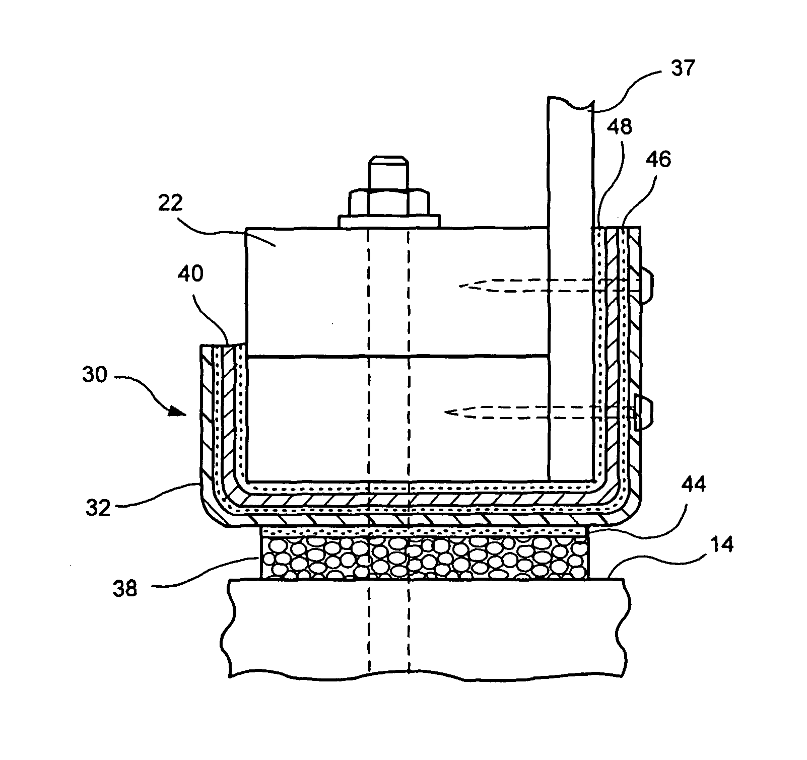
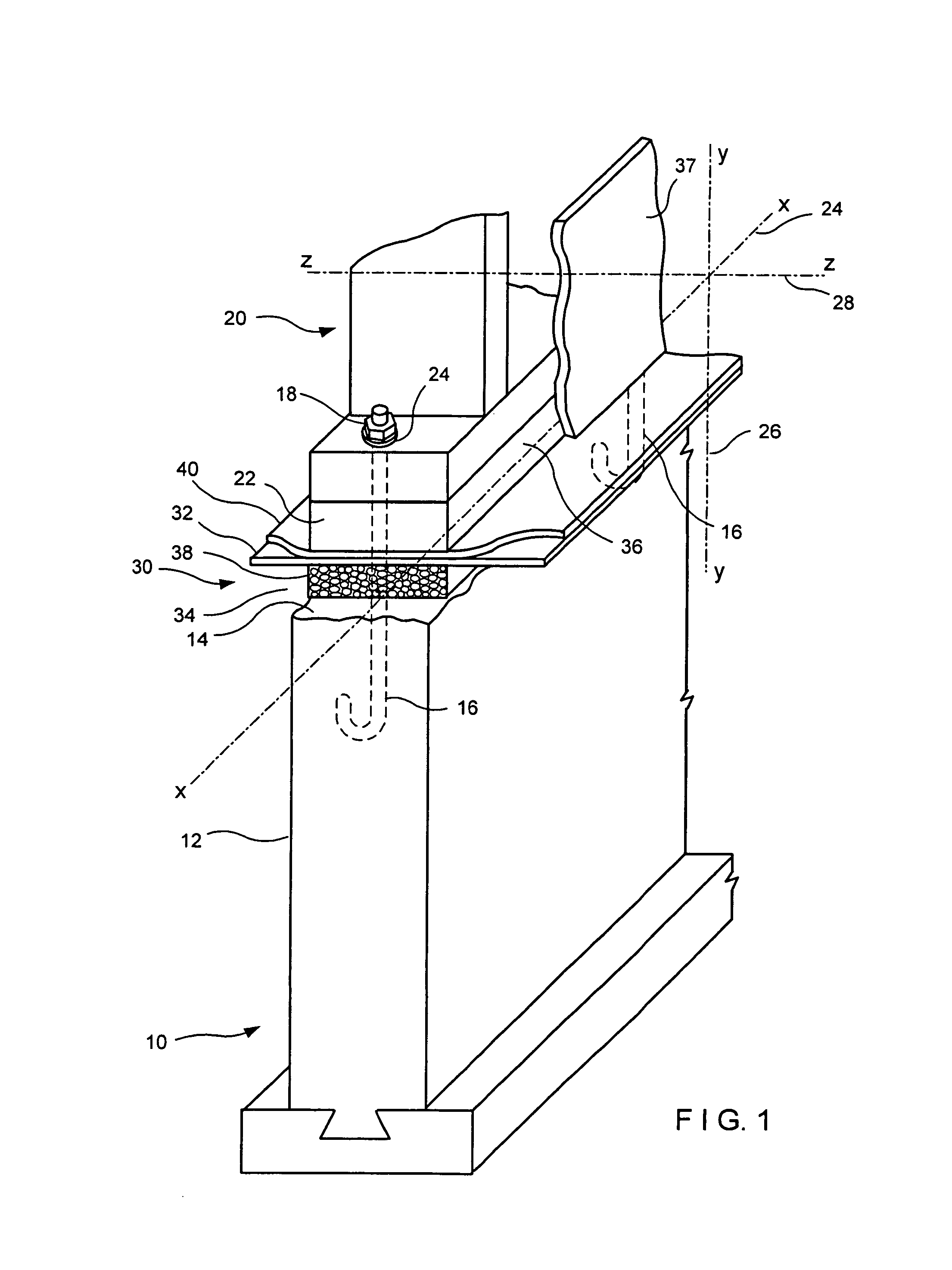
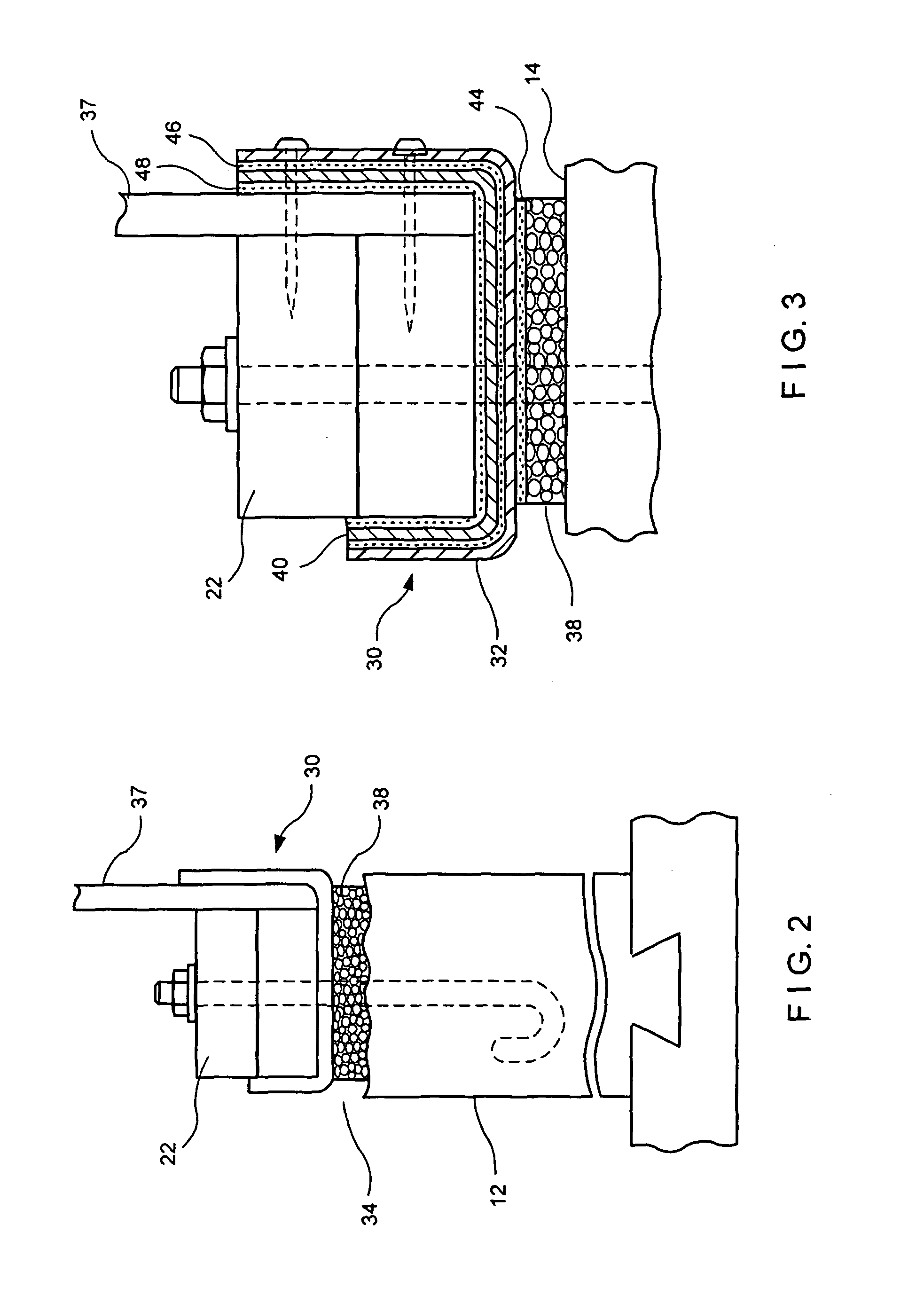
In the sill seal and termite shield (SSTS) of this invention, pressure-activated adhesives are used to attach a combination device of a foam sill seal, a waterproofing membrane, and a termite shield to at least one side of the sill plate and to the uppermost surface of the foundation. The SSTS is emplaced atop the foundation and receives thereon a sill plate. The weight of the sill plate pushes the foam cells of the sill seal into the irregular surface of the foundation wall and anchors the waterproofing membrane and the termite shield. The barrier function of the termite shield portion increases the longevity of the sill plate by precluding penetration thereof by termites and other wood boring insects. The weatherproofing membrane is of a high tensile strength material thereby improving tear and puncture resistance.

Referring now to FIGS. 1 through 4, the first embodiment of this invention in which a poured concrete foundation, referred to generally by the reference designator 10, i...


PUM


Abstract

Sill seal and termite shield (SSTS) devices are disclosed. SSTS devices for residential housing are shown for poured concrete, masonry block, and frost protected shallow foundations. The polymeric foam pad of the SSTS device seals the rough foundation wall surface. For the termite shield function, the SSTS devices use a metallic web—either foil or an impenetrable screen—or a nonmetallic web—either plastic sheet or impenetrable scrim. The termite shield or barrier layer is shown as adjacent to a weatherproofing membrane or as an interior layer of an polymeric laminate weatherproofing membrane. Hot melt adhesives attach the foam pad to the weatherproofing membrane and, where applicable, the barrier layer to the weatherproofing membrane. Pressure-activated, hot melt adhesives attach the SSTS device to the sill plate. A release sheet is applied forming a peel-and-stick device.

Description

BACKGROUND OF THE INVENTION1. Field of the InventionThis invention relates to a dual-purpose device for sealing the space between a foundation and a sill plate and for providing a physical barrier against termites and other wood boring insects. The device has a portion thereof that adheres to the open face of the sill plate and acts as an impenetrable shield. More particularly, the invention includes a strip of polymeric material that provides sill sealing and precludes weather and insect penetration.2. Description of the Prior ArtBefore the introduction of seismic building codes, residential and small commercial structures were not required to have the sill plate bolted to the concrete foundation. In California, homes built before 1949 were not covered by any specific seismic building code. Upon seismic activity, in buildings which are not bolted to the foundation, the building structure may move on the foundation or even slip off the foundation. Such movement can cause extensive d...

Claims


Application Information

Patent Timeline
Patent Type & Authority Patents(United States)
IPC IPC(8): A01K13/00
CPCE04B1/2604E04B1/66E04B1/72E04B2001/268E04B2001/2684
Inventor HOHMANN, JR., RONALD P.
Owner HOHMANN & BARNARD INC
Why Eureka
Try Eureka