
Multistation device for mixing the contents of laboratory vessels

a multi-station device and laboratory technology, applied in the direction of mixing, transportation and packaging, chemistry apparatus and processes, etc., can solve the problems of increasing the weight of the device as a whole, causing problems, and causing problems

Active Publication Date: 2011-09-13
EPPENDORF SE
View PDF20 Cites 16 Cited by
  • Summary
  • Abstract
  • Description
  • Claims
  • Application Information

AI Technical Summary

Benefits of technology

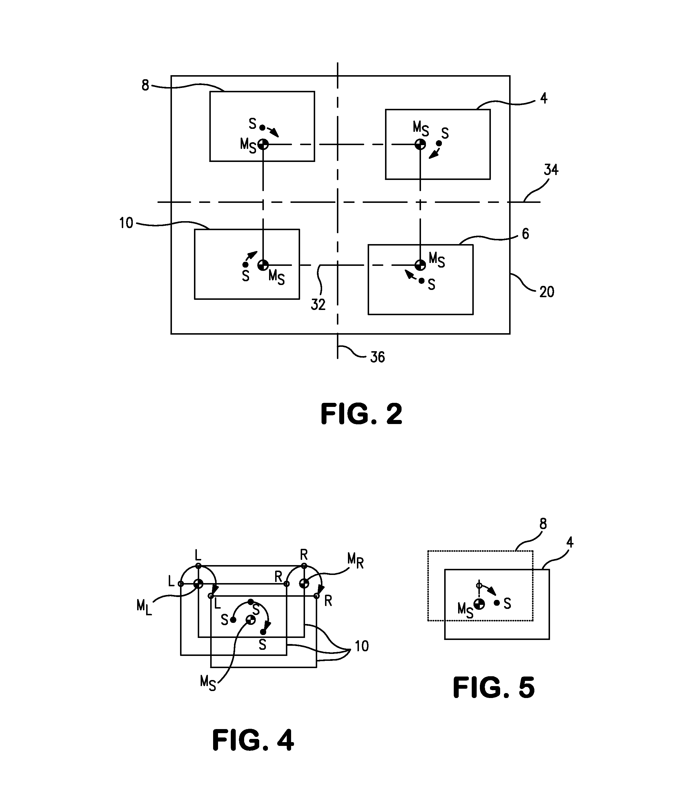
[0011]The drive mechanism of the mixing device according to the invention is capable of moving the adapter plate in a mixing movement which oscillates in a circular and translatory manner in a plane. “Oscillates in a circular and translatory manner” can in other words be described by the fact that, in such a mixing movement according to the invention, each point of the adapter plate executes a circular movement with the same radius, the same angular speed and the same angular position about a respective midpoint in parallel planes. The mixing movement takes place in horizontal planes, with the result that exchangeable thermoblocks received in the adapter plates are mixed in an operationally reliable manner with reaction vessels arranged upright in them.
[0018]It will be noted in general that the imbalance compensation achieved according to the invention may not physically function in an ideal way, because the adapter plates may be charged with different loads. It is therefore advantageous, according to the invention, that the imbalances according to the invention at least partially compensate each other and / or are at least reduced in rotation phase.

Problems solved by technology

The imbalance problem arises physically from the described circular mixing movement.
Even in a single-station mixer, a counterweight of this kind represents an additional structural part that has to be adjusted during assembly and that further increases the weight of the device as a whole.
In multistation mixers, this problem multiplies, so to speak, with the number of adapter plates of the multistation mixing device.

Method used


Image

  • Multistation device for mixing the contents of laboratory vessels
  • Multistation device for mixing the contents of laboratory vessels
  • Multistation device for mixing the contents of laboratory vessels

Examples


Embodiment Construction

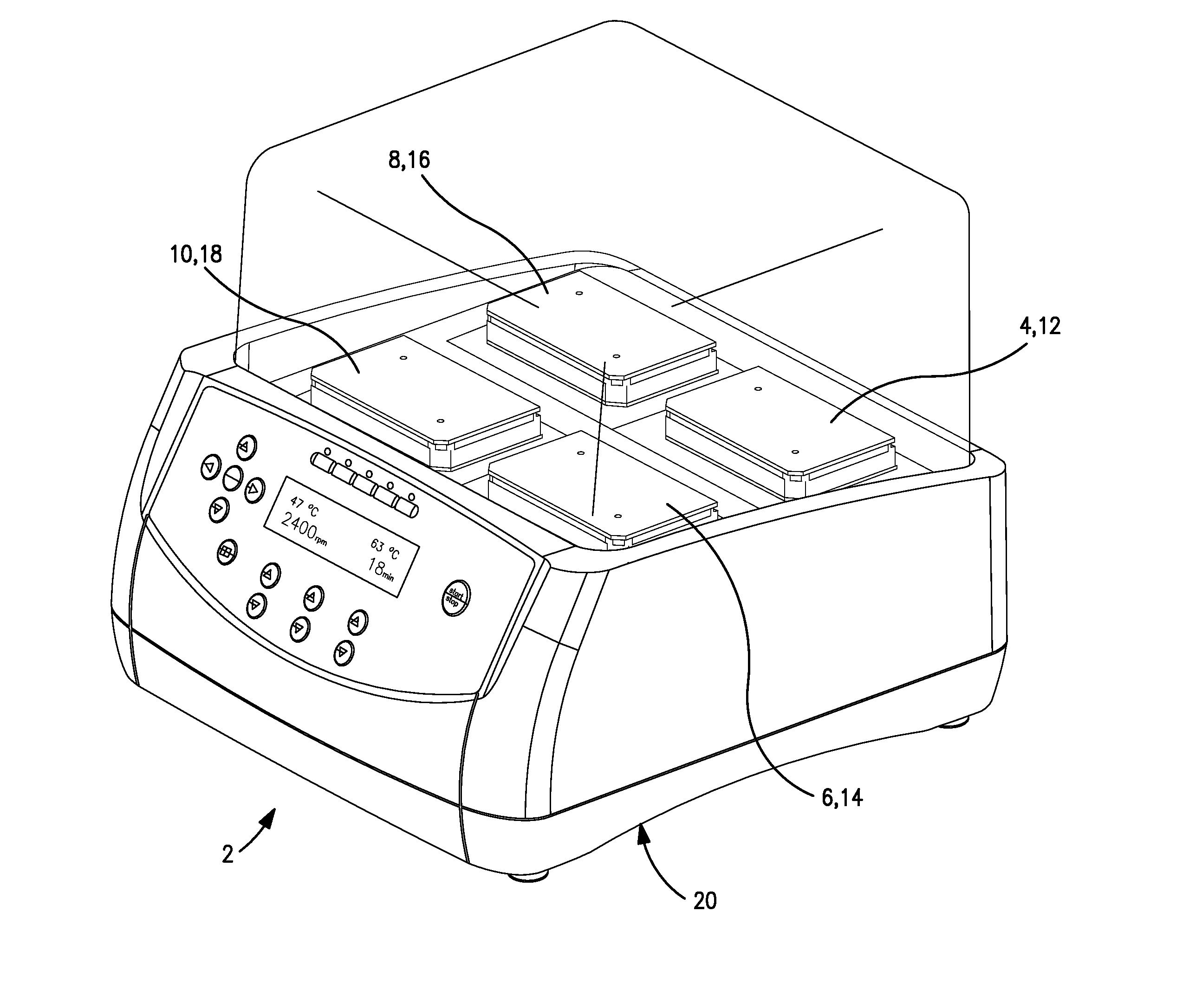
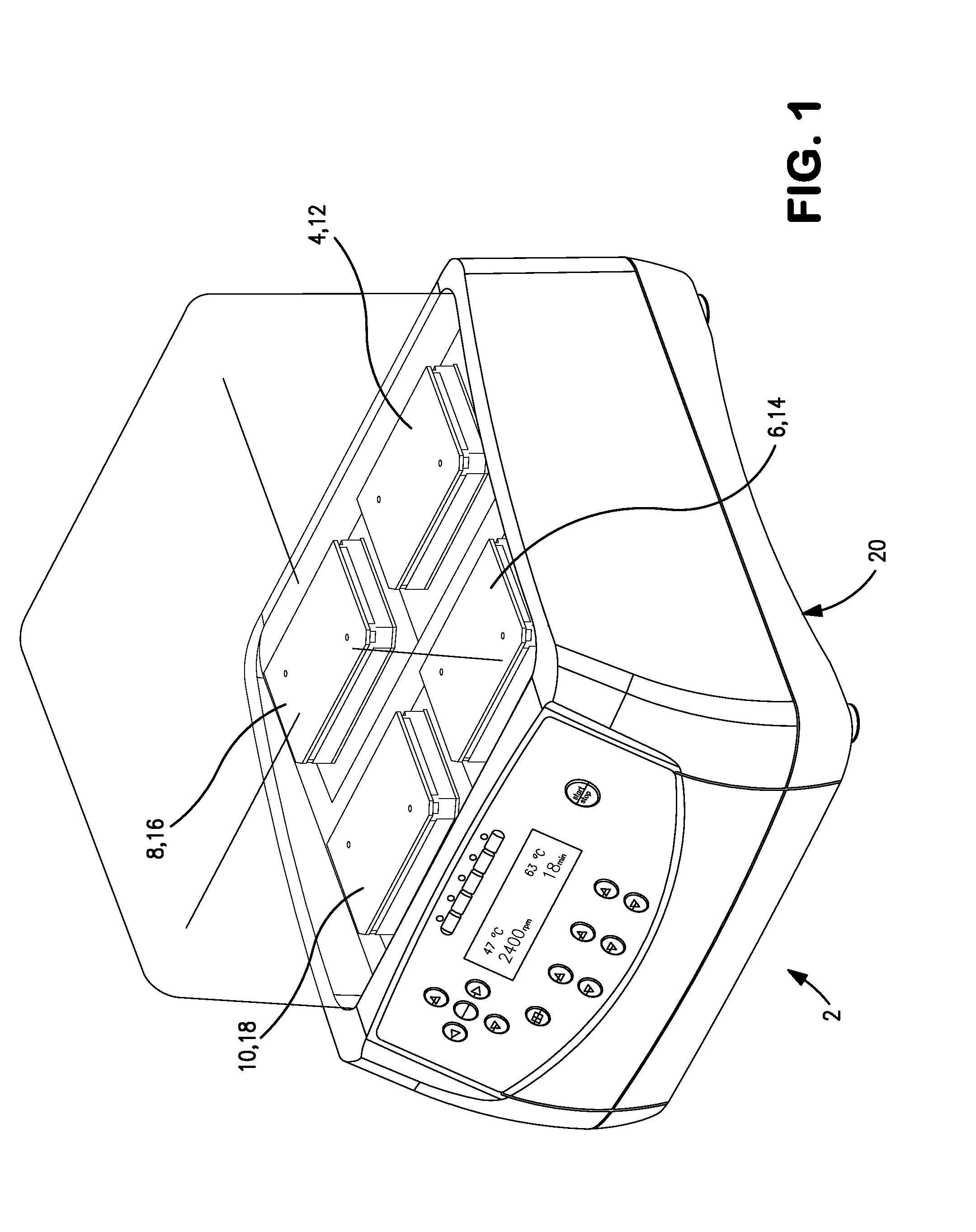
[0025]In FIG. 1, a mixing device 2 can be seen with four frame-shaped adapter plates 4, 6, 8 and 10 which are arranged on the top and which each have a holder for receiving exchangeable thermoblocks 12, 14, 16 and 18. By means of a drive mechanism inside a housing 20 of the mixing device 2, each of the adapter plates can be driven in a mixing movement that takes place with the same angular speed of each adapter plate 4, 6, 8 and 10, such that, in a horizontal plane, each point of a respective adapter plate executes a circular movement with the same radius, the same angular speed and the same angular position about a respective midpoint (circular translatory oscillating mixing movement). The drive mechanism 22, provided for this purpose in the mixing device 2, and the bearings 24, 26, 28 and 30 of the adapter plates 4, 6, 8 and 10 are shown in FIG. 3, and a schematic representation of the circular translatory oscillating mixing movement can be seen in FIG. 4.

[0026]Referring first to ...


PUM


Abstract

The invention relates to a multistation mixing device for mixing the contents of laboratory vessels. The device comprises at least two adapter plates having a holder for receiving laboratory vessels and a drive mechanism capable of driving the adapter plates in a mixing motion with the same angular speed such that, in horizontal planes, each point of the adapter plates performs a circular motion with the same radius, the same angle speed and the same angular position around a respective center. The starting positions of the adapter plates, from which the adapter plates are driven by the drive mechanism, are rotated relative to one another by an angle in the direction of the mixing motion in their respective angular position, such that imbalances occurring during the mixing motion are at least partially compensated.

Description

FIELD OF THE INVENTION[0001]The present invention relates to a device for mixing the contents of laboratory vessels in particular, with at least two adapter plates, each with a holder for receiving vessels, in particular laboratory vessels in exchangeable thermoblocks, and with a drive mechanism, by means of which each of the adapter plates can be driven with the same angular speed in a mixing movement which oscillates in a circular translatory manner in a horizontal plane.[0002]Mixing devices in which the contents of vessels are mixed are sufficiently well known. For laboratories in particular, there are mixers that can also mix small amounts of liquid by virtue of the fact that small containers are also combined in very large groups of tens, hundreds or even thousands in suitable holders, called “exchangeable thermoblocks”. Such exchangeable thermoblocks and also the reaction vessels can be standardized. For example, there are reaction vessels with a content of 0.2 ml, 0.5 ml, 1.5...

Claims


Application Information

Patent Timeline
IPC IPC(8): B01F11/00B01L99/00
CPCB01F9/0021B01F11/0088B01F2215/0037G01N2035/00524B01F29/322B01F31/445B01F2101/23
Inventor EBERS, MANFREDPETERSEN, BERND
Owner EPPENDORF SE
Learn More