Instruments and techniques for guiding instruments to a spinal column

a technology of guiding instruments and spinal columns, applied in the field of spinal column guiding instruments, can solve the problems of reducing the height of the disc space affecting the function of the disc,

Inactive Publication Date: 2011-09-13
WARSAW ORTHOPEDIC INC
View PDF32 Cites 4 Cited by
  • Summary
  • Abstract
  • Description
  • Claims
  • Application Information

AI Technical Summary

Benefits of technology

[0006]In another aspect, a method for guiding instruments to a disc space between a cephalad vertebra and a caudal vertebra comprises: biasing a caudal member of a reference guide instrument into engagement with an endplate of the caudal vertebra with a guiding portion of the reference guide instrument extending along a reference axis in parallel relation to the endplate of the caudal vertebra, wherein the caudal member includes a height between an endplate contacting surface and an opposite surface that is substantially less than a height of the disc space between endplates of the cephalad and caudal vertebrae; and guiding a preparation instrument along the guiding portion and reference axis to a location adjacent the cephalad and caudal vertebrae.
[0007]According to another aspect, a method for guiding instruments to a disc space between a cephalad vertebra and a caudal vertebra comprises: positioning a reference mechanism of a reference guide instrument in the disc space with a guiding portion of the reference guide instrument extending proximally from the disc space; engaging a caudal member of the reference mechanism against an endplate of the caudal vertebra with a reference axis of the guiding portion extending parallel to the endplate of the caudal vertebra and with the caudal member including a height therealong that is less than a height of the disc space between endplates of the cephalad and caudal vertebrae so that the caudal member is spaced from the endplate of the cephalad vertebra when engaged to the endplate of the caudal vertebra; and guiding a preparation instrument along the guiding portion and reference axis to a location adjacent the cephalad and caudal vertebrae.

Problems solved by technology

The spinal discs may be displaced or damaged due to trauma, disease or aging.
A herniated or ruptured annulus fibrosis may result in nerve damage, pain, numbness, muscle weakness, and even paralysis.
Furthermore, as a result of the normal aging processes, discs dehydrate and harden, thereby reducing the disc space height and producing instability of the spine and decreased mobility.
Proper alignment and attachment of the implants can be difficult because of variations in the shape and contours of the vertebral body.
Poor surface contact between the device and the vertebral body results if the device is mounted over variations in the surface of the vertebral body.

Method used


Image

  • Instruments and techniques for guiding instruments to a spinal column
  • Instruments and techniques for guiding instruments to a spinal column
  • Instruments and techniques for guiding instruments to a spinal column

Examples


Embodiment Construction

[0016]For the purposes of promoting an understanding of the principles of the present invention, reference will now be made to the embodiments illustrated in the drawings, and specific language will be used to describe the same. It will nevertheless be understood that no limitation of the scope of the invention is intended thereby. Any alterations and further modification in the described processes, systems, or devices, and any further applications of the principles of the invention as described herein are contemplated as would normally occur to one skilled in the art to which the invention relates.

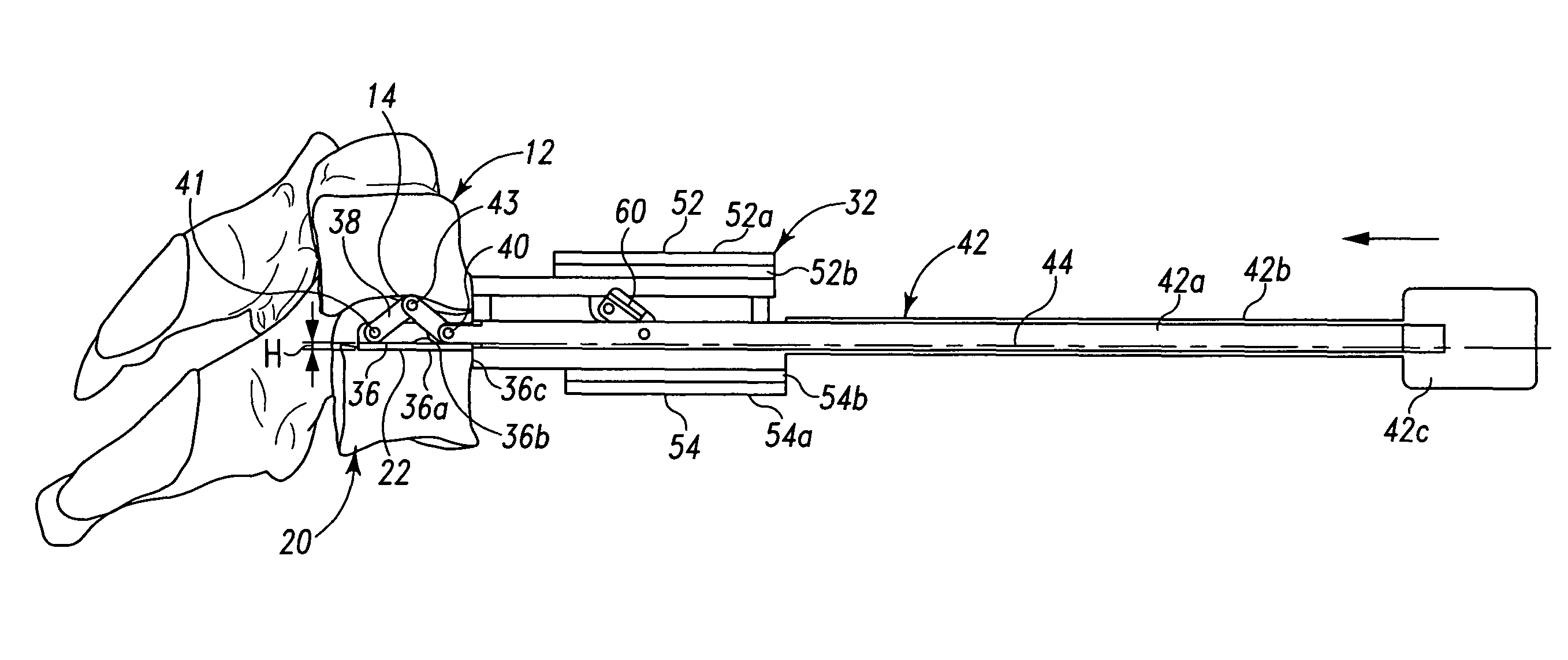
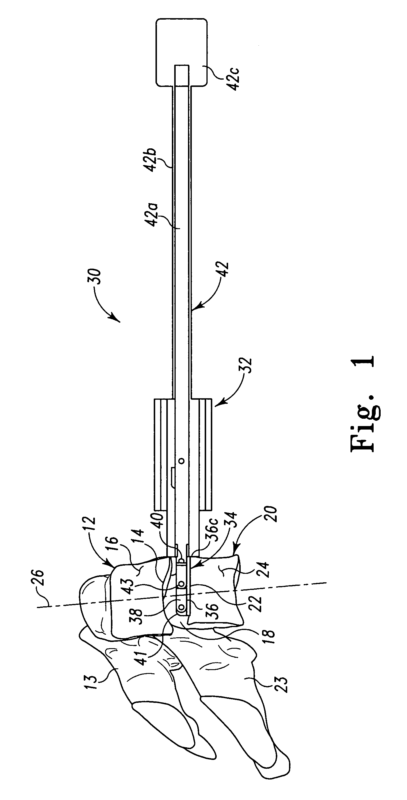
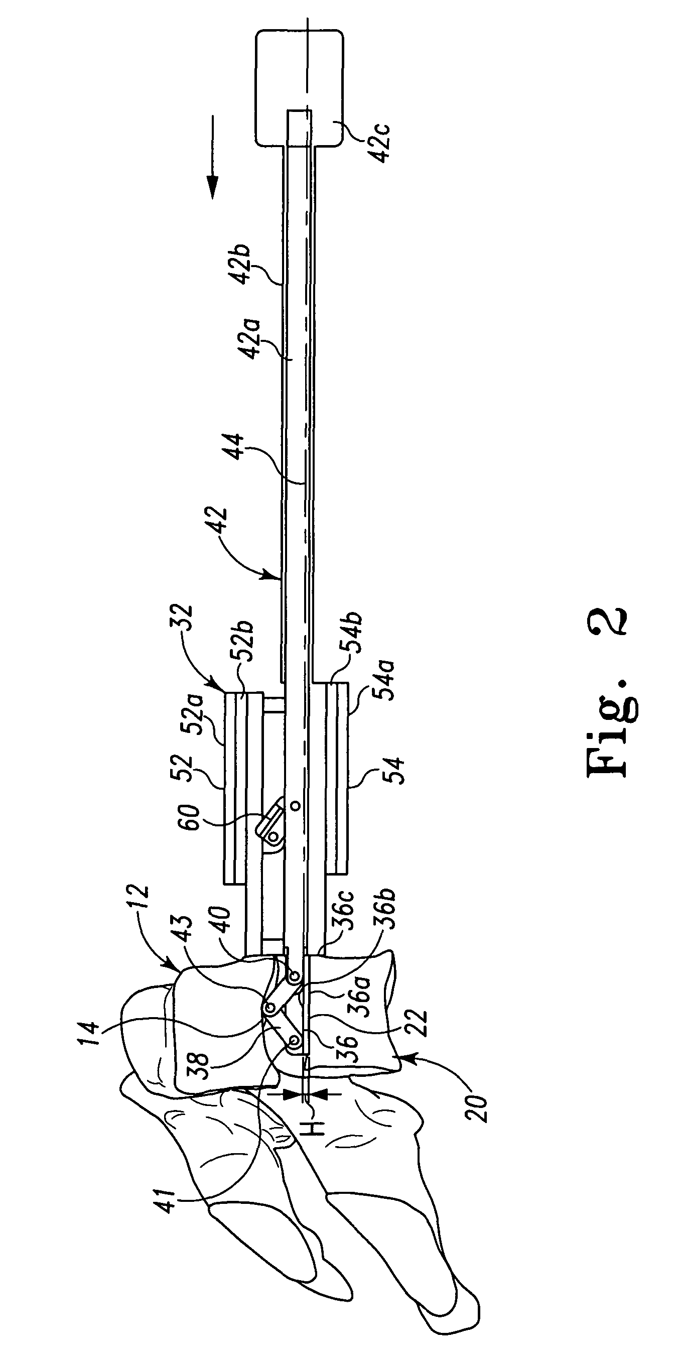
[0017]The present invention is directed to a system and method of shaping and contouring a perimeter surface of a vertebral body for receipt of an implant. The shaped surface can include any one or combination of the endplate of a cephalad vertebra, the surfaces of the cephalad vertebra outside the disc space, the endplate of a caudal vertebra, and surfaces of the caudal vertebra outside ...


PUM


Abstract

Systems and methods of shaping surfaces of vertebral bodies include a reference guide instrument that can be positioned relative to a disc space between vertebral bodies and referenced to the caudally located endplate of the disc space. The reference guide instrument can then be employed to guide preparation instruments to the vertebral bodies in an orientation and spacing referenced to the caudal endplate of the subject disc space to shape vertebral surfaces to receive an implant.

Description

BACKGROUND[0001]Normal intervertebral discs between endplates of adjacent vertebrae distribute forces between the vertebrae and cushion vertebral bodies. The spinal discs may be displaced or damaged due to trauma, disease or aging. A herniated or ruptured annulus fibrosis may result in nerve damage, pain, numbness, muscle weakness, and even paralysis. Furthermore, as a result of the normal aging processes, discs dehydrate and harden, thereby reducing the disc space height and producing instability of the spine and decreased mobility. Most surgical corrections of a disc space include a discectomy, which can be followed by restoration of normal disc space height and bony fusion of the adjacent vertebrae or disc replacement between the adjacent vertebrae to maintain the disc space height and motion. Procedures may also involve, either alone or in conjunction with intradiscal implants, positioning implants that extend extradiscally along one or more vertebrae.[0002]Proper alignment and ...

Claims


Application Information

Patent Timeline
Patent Type & Authority Patents(United States)
IPC IPC(8): A61F5/00A61B17/90A61B19/00
CPCA61B17/1757
Inventor GIL, CARLOS E.SASSO, RICK C.DACE, MARK C.
Owner WARSAW ORTHOPEDIC INC
Why Eureka
Try Eureka