Inductor and method of operating an inductor by combining primary and secondary coils with coupling structures

a technology of inductor coil and coupling structure, which is applied in the field of inductor coil tunable, can solve the problems of reducing the cmax/cmin-ratio of the actual tuning varactor, the application of lc vcos is rather difficult, and the method is limited in practice, so as to improve the granularity of the switched inductance, improve the granularity of the tuning step, and improve the granularity of the area consumption

Active Publication Date: 2011-09-13
TAIWAN SEMICON MFG CO LTD
View PDF14 Cites 20 Cited by
  • Summary
  • Abstract
  • Description
  • Claims
  • Application Information

AI Technical Summary

Benefits of technology

[0018]It is yet a further object of the invention to present an inductor with improved area consumption.
[0019]According to an aspect of the present invention, an inductor is provided. The inductor includes: a primary coil; at least one secondary coil having at least one loop winding with two open-circuited ports; at least one coupling coil having at least one loop winding with two open-circuited ports and a switch located between the two open-circuited ports which is arranged to selectively close the loop winding of at least one coupling coil; at least one passive coupling structure having at least one coupling coil arranged between the primary coil and the secondary coils and / or between two of the secondary coils; where the primary coil is coaxially arranged and operated in parallel to one or more isolated secondary coils and at least one coupling coil is radially displaced from the primary and one of the secondary coils so that the whole coupling coil is lying between adjacent loop windings of two of the secondary coils and / or between adjacent loop windings of the primary coil and one of the secondary coils. By passively coupling the primary coil and at least one secondary coil and / or at least two secondary coils, i.e. by magnetically coupling the primary coil and at least one secondary coil and / or at least two secondary coils when closing the switch between the open-circuited ports of a coupling coil, the mutual inductance of the inductor is changed and thus the overall inductance is varied in intermediate steps resulting in a finer granularity of tuning steps.
[0020]According to another aspect of the present invention, an inductor is provided. The inductor includes: a primary coil; at least one secondary coil having at least one loop winding with two open-circuited ports; at least one coupling coil having at least one loop winding with two open-circuited ports and a switch located between the two open-circuited ports which is arranged to selectively close the loop winding of at least one coupling coil; at least one active coupling structure; where the primary coil is coaxially arranged and operated in parallel to one or more isolated secondary coils and at least one active coupling structure is arranged between the primary coil and at least one secondary coil and / or between at least two secondary coils, to selectively parallel couple the primary coil and one of the secondary coils and / or to selectively parallel couple at least two of the secondary coils. By active parallel coupling of two coaxially arranged coils, i.e. by electrically parallel connecting the primary coil and at least one secondary coil and / or at least two secondary coils with each other, the inductance varies compared to the inductance of one of the coils as well as to the inductance of both coils. Thus, an intermediate inductance is generated allowing reduction of the step size of the switchable inductance. Therefore, a tunable inductor according to the invention provides a wide inductance tuning range by the application of active coupling structures between one primary coil and at least one secondary coil, and / or between at least two secondary coils. By parallel coupling of two coaxially arranged coils, the inductance varies compared to the inductance of one of the coils as well as to the inductance of both coils. Thus, an intermediate inductance is generated allowing reduction in the step size of the switchable inductance.

Problems solved by technology

In wireline communication however where multiple standards with partially widely spaced frequency ranges often have to be covered, the application of LC VCOs is rather difficult since the tuning range of LC-tank oscillators is limited to about 30% if regular LC-tank topologies are used.
However, this method is limited in practice by the capacitive and resistive parasitics that occur when increasing the number of varactor banks.
The additional capacitive parasitics would decrease the Cmax / Cmin-ratio of the actual tuning varactor and the resistive parasitics would degrade the quality factor disproportionately because of the longer wiring traces required to connect the different varactor banks to the inductor coil and the other devices of the LC VCO.
However, switching of inductor coils does degrade the quality factor because of the resistive losses of the closed switches.
This statement is valid up to a certain frequency but at extremely high frequencies the LC VCO cannot operate anymore because of frequency divider limitations in a PLL circuit.
Additionally other parasitics like bridging capacitances across the inductors come into play and degrade the quality factor.
However, within a reasonably wide frequency range however the performance of a switchable inductor outperforms that of a switchable varactor bank.
However, in such cases, the tuning range obtained by known inductor / varactor tuning circuit is limited and the step size of switched inductance is relatively coarse.

Method used


Image

  • Inductor and method of operating an inductor by combining primary and secondary coils with coupling structures
  • Inductor and method of operating an inductor by combining primary and secondary coils with coupling structures
  • Inductor and method of operating an inductor by combining primary and secondary coils with coupling structures

Examples


Embodiment Construction

[0036]Preferred embodiments of the invention are described in detail below, by way of example only, with reference to the following drawings.

[0037]Any disclosed embodiment can be combined with one or several of the other embodiments shown and / or described. This is also possible for one or more features of the embodiments.

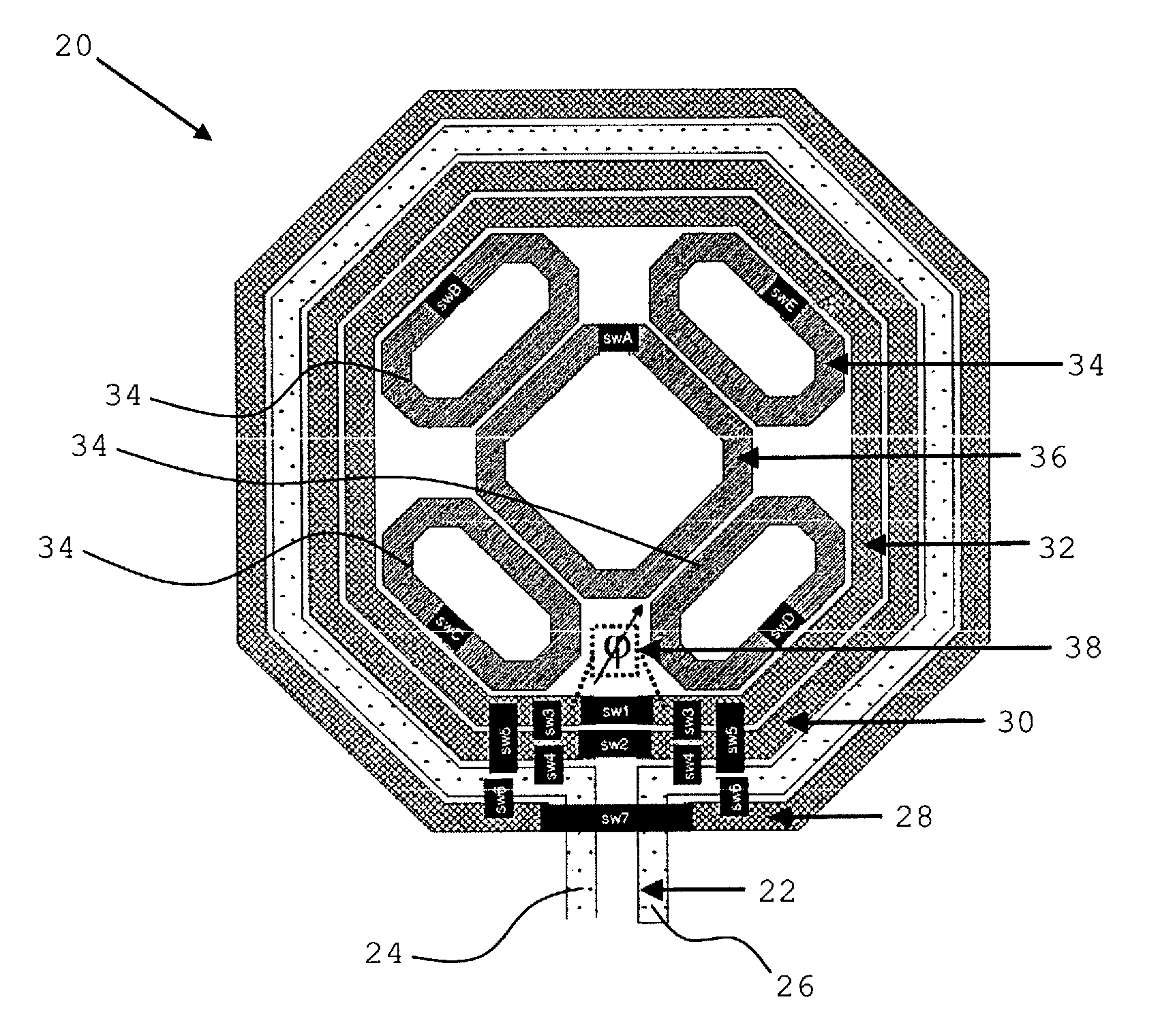
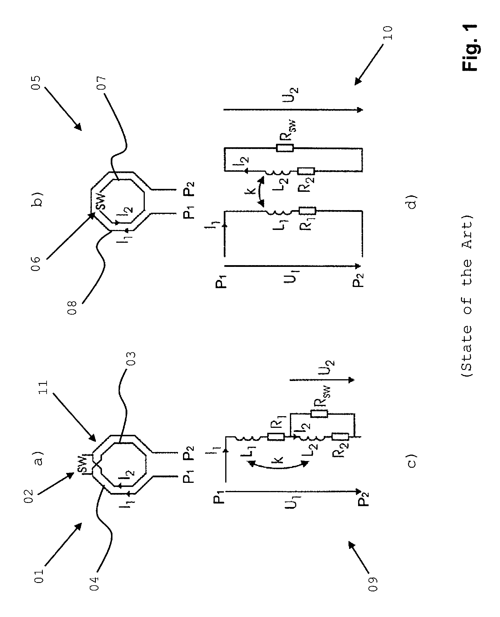
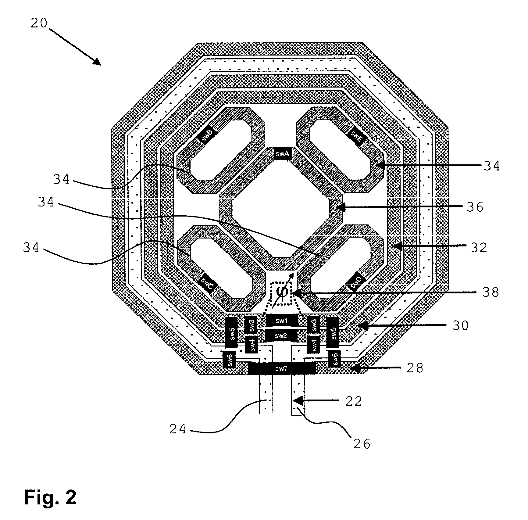
[0038]According to an embodiment of the invention, at least one active coupling structure is arranged between the primary coil and at least one secondary coil and / or between at least two of the secondary coils, to selectively parallel couple the primary coil and at least one secondary coil and / or to selectively parallel couple at least two of the secondary coils.

[0039]By the active parallel coupling of two coaxially arranged coils, i.e. by electrically parallel connecting the primary coil and at least one secondary coil and / or at least two secondary coils with each other, the inductance varies compared to the inductance of one of the coils as well as to the inductan...


PUM

PropertyMeasurementUnit
phase noise performanceaaaaaaaaaa
frequencyaaaaaaaaaa
capacitanceaaaaaaaaaa

Abstract

An inductor and method of operating the inductor by combining primary and secondary coils with passive coupling, active parallel, or active cross-coupling structures. The first includes at least one passive coupling structure having at least one coupling coil arranged between a primary coil and at least one of the secondary coils and / or between two of the secondary coils. The second includes an active coupling structure arranged between a primary coil and at least one secondary coil and / or between at least two of the secondary coils, to selectively parallel couple the primary coil and one of the secondary coils and / or at least two of the secondary coils. The third includes an active coupling structure to selectively cross couple a primary coil and at least one of the secondary coils and / or to selectively cross couple at least two of the secondary coils.

Description

CROSS-REFERENCE TO RELATED APPLICATION[0001]This application claims priority under 35 U.S.C. §119 from European Patent Application No. 08101518.2 filed Feb. 12, 2008, the entire contents of which are incorporated herein by reference. This application further claims priority under 35 U.S.C. §119 from European Patent Application No. 08101516.6 filed Feb. 12, 2008, the entire contents of which are incorporated herein by reference. Still further, this application claims priority under 35 U.S.C. §119 from European Patent Application No. 08101520.8 filed Feb. 12, 2008, the entire contents of which are incorporated herein by reference.BACKGROUND OF THE INVENTION[0002]1. Field of the Invention[0003]The present invention generally relates to the design of tunable inductor coils used in inductance-capacitance (Ic) tank voltage controlled oscillators (vco) and phase-locked-loop (pll) circuits. More particularly, the present invention relates to an inductor and method of operating the inductor ...

Claims


Application Information

Patent Timeline
Patent Type & Authority Patents(United States)
IPC IPC(8): H01F5/00
CPCH03H7/185
Inventor KOSSEL, MARCEL A.MORF, THOMAS E.SCHMATZ, MARTIN LEOWEISS, JONAS R.
Owner TAIWAN SEMICON MFG CO LTD
Why Eureka
Try Eureka