
Method and system for display of structures or regions of interest

a technology for displaying structures and regions, applied in image enhancement, instruments, recognition of medical/anatomical patterns, etc., can solve the problems of inefficiency of automated editing tools, affecting the growth of the region, and requiring a significant amount of learning for automated editing tools, etc., to achieve the effect of reducing the size of the grown region, preventing the growth of the region, and being convenient to us

Active Publication Date: 2011-09-13
GENERAL ELECTRIC CO
View PDF19 Cites 13 Cited by
  • Summary
  • Abstract
  • Description
  • Claims
  • Application Information

AI Technical Summary

Benefits of technology

"The invention provides a method and system for displaying structures or regions of interest in an image. The system includes a graphic user interface displayable on a computer screen, with virtual buttons selectable by a user to control the processing of the image. The user can select a virtual button to extract a structure or region of interest by starting from a marker point. The system displays a window where the extracted structure or region of interest is displayed as it grows. The method is easy to use and allows the user to stop the growth of the region of interest at any time. The technical effect of the invention is to provide a more intuitive and efficient way to extract relevant structures or regions of interest from images."

Problems solved by technology

Editing a 3D image to create segmentation is often the most time consuming part of generating a useable 3D image.
These tools have the following disadvantages: automated editing tools require a significant amount of learning about how to use them by the user; automated editing tools are not efficient in all situations; manual editing tools are difficult to use, and editing a 3D volume takes a long time if good results are to be obtained; and the quality of results obtained with manual editing tools depends on the user.
These tools are becoming more and more open to criticism as the size of data sets supplied by the acquisition devices increases.
The increase in the size of data sets increases the time necessary to extract a region of interest.

Method used


Image

  • Method and system for display of structures or regions of interest
  • Method and system for display of structures or regions of interest
  • Method and system for display of structures or regions of interest

Examples


Embodiment Construction

[0021]One purpose of the method and system for displaying regions of interest is to provide for the reduction of the time necessary for a user to obtain useable images and to reduce dependence of the system with regard to the user.

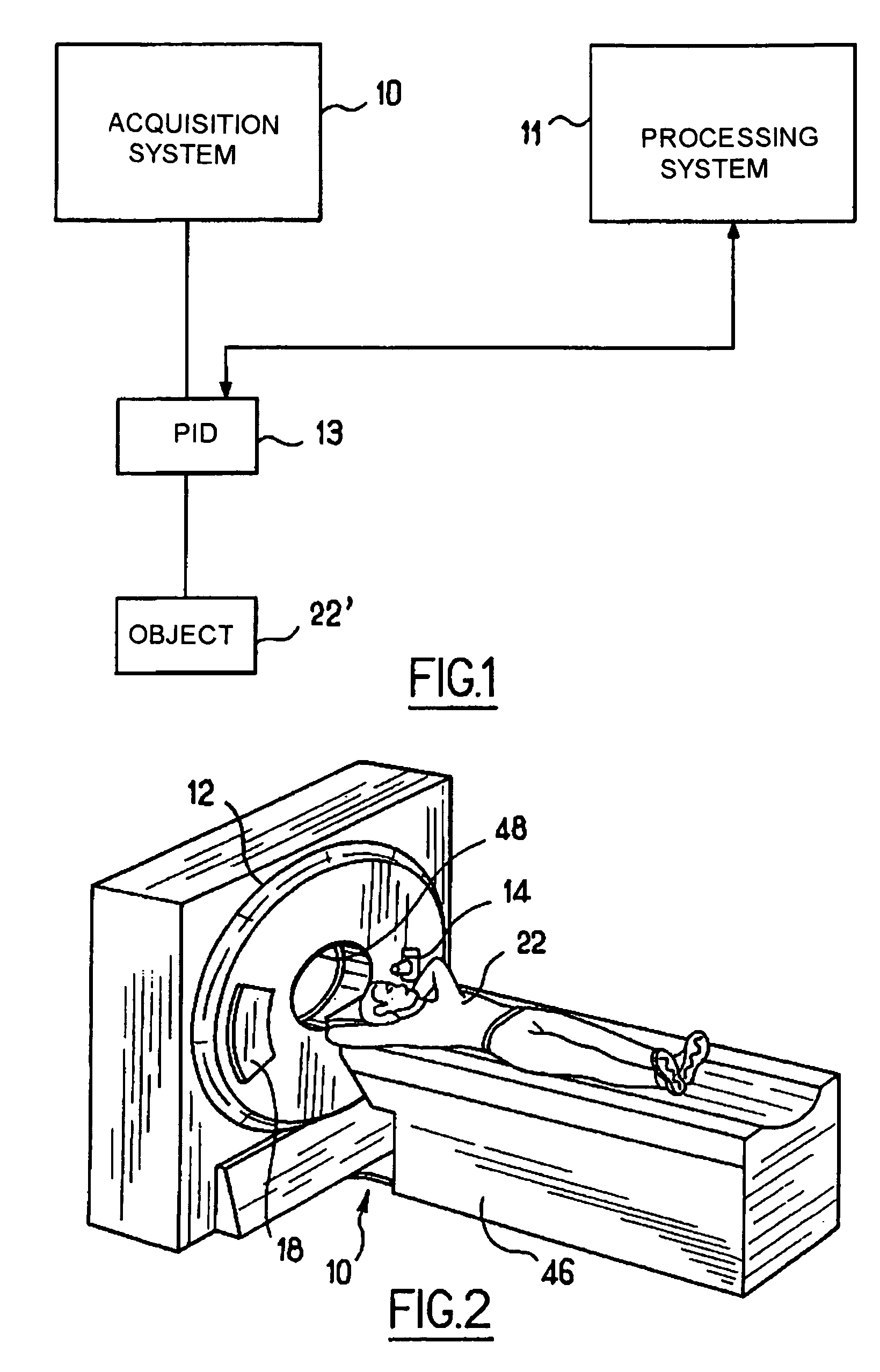
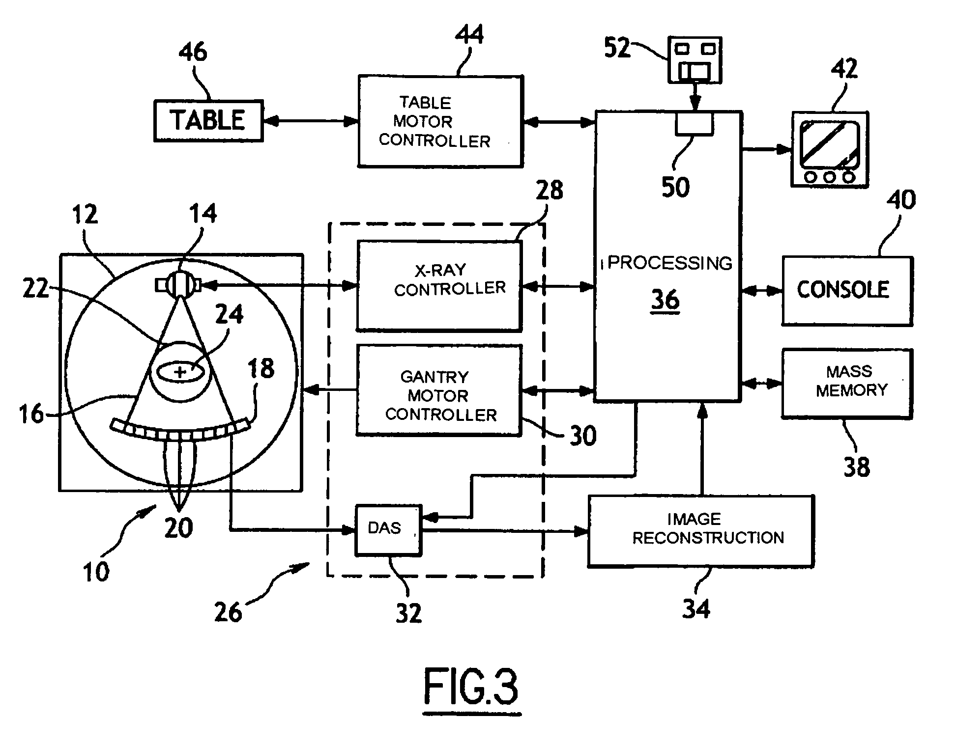
[0022]FIG. 1 illustrates a principle diagram for an arrangement that can be used for acquisition of an image and processing of the acquired image in order to extract regions of interest. The arrangement comprises an image acquisition system 10, an image processing system 11, and a physiological information device 13 (PID). The image acquisition system 10 may for example be an ultrasound image acquisition system, a magnetic resonance image (MRI) acquisition system, a single photon emission computed tomography (SPECT) image acquisition system, a tomodensitometry (TDM) image acquisition system, or a positron emission tomography (PET) image acquisition system.

[0023]The image processing system 11 may be integrated into the image acquisition system 10 or it may ...


PUM


Abstract

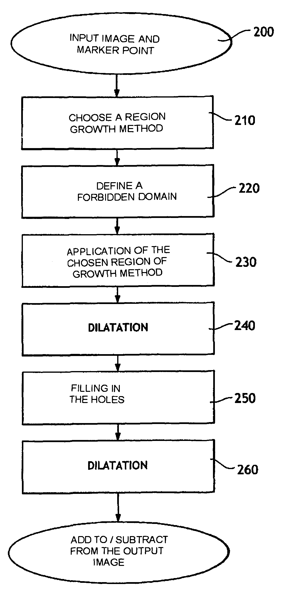
A system and a method for extracting regions of interest from a medical image in order to obtain an image useable by a user. The system includes a user interface comprising virtual buttons that the user can select using an input, the buttons enabling the user to control a selected region extraction method using a region growth method to extract a region The region extraction method depend on which virtual buttons are selected by the user. The user interface also includes a window in which the result of extraction of the region of interest can be displayed, as the region is being grown.

Description

CROSS-REFERENCE TO RELATED APPLICATIONS[0001]This application claims the benefit of a priority under 35 USC 119 (a)-(d) to French Patent Application No. 04 13941 filed Dec. 27, 2004, the entire contents of which are hereby incorporated by reference.BACKGROUND OF THE INVENTION[0002]An embodiment of the present invention is directed to a method and system for display of structures or regions of interest. In particular, an embodiment of the present invention is related in general to images that may be associated with heart examinations by ultrasounds, magnetic resonance, tomography by single photon emission, tomodensitometry, and by positron emission tomography. More particularly, an embodiment of the present invention applies to methods and systems for automating the display of structures or regions of interest.[0003]Editing a 3D image to create segmentation is often the most time consuming part of generating a useable 3D image. The segmentation of an image comprises extracting region...

Claims


Application Information

Patent Timeline
Patent Type & Authority Patents(United States)
IPC IPC(8): G06K9/00G06T15/00
CPCG06K9/342G06T7/0081G06T7/0091G06K2009/366G06K2209/05G06T2207/10072G06T2207/10132G06T2207/20092G06T2207/30048G06T7/11G06T7/155G06V10/248G06V10/267G06V2201/03
Inventor KNOPLIOCH, JEROMEPOUPON, FABRICE
Owner GENERAL ELECTRIC CO
Learn More