Steering control system

a control system and steering device technology, applied in the direction of steering parts, non-deflectable wheel steering, vehicle components, etc., can solve the problem that the design does not include the piloting of the hydraulic pump with the steering device of the vehicle, and achieve the effect of saving manufacturing costs

Active Publication Date: 2011-09-20
BLUE LEAF I P INC
View PDF9 Cites 0 Cited by
  • Summary
  • Abstract
  • Description
  • Claims
  • Application Information

AI Technical Summary

Benefits of technology

[0004]The invention relates to a steering system for crawlers and wheeled tractor of the type disclosed in which the hydraulic pump controlling the flow of the hydraulic fluid fed to the hydraulic units associated with the axle shafts may be piloted in a simple and economic manner by the steering device of the vehicle.
[0005]This configuration may have advantages in minimizing control power losses due to steering command while also minimizing noise transfer into the inside of cab environment and providing reactive control over steering, to have full awareness of the steering system functional conditions and yield.
[0007]The actuator responsive to a rotation of the steering wheel of the vehicle makes possible to control the control unit of the steering system in a simple way without requiring consumption of energy.
[0008]Particularly, when it is used in a crawler, the steering system according to the invention makes possible to drive the crawler like a conventional land vehicle.
[0009]Furthermore, the steering system according to the invention may be implemented on both wheeled and crawler tractors making possible to standardize the manufacturing of both types of tractors with substantial saving of manufacturing costs.

Problems solved by technology

These designs however do not incorporate how to pilot the hydraulic pump with the steering device of the vehicle, for instance by a steering wheel.

Method used


Image

  • Steering control system
  • Steering control system
  • Steering control system

Examples


first embodiment

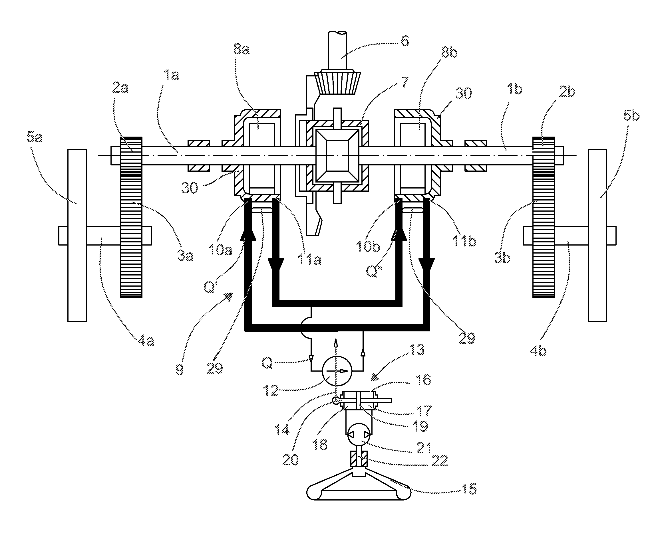
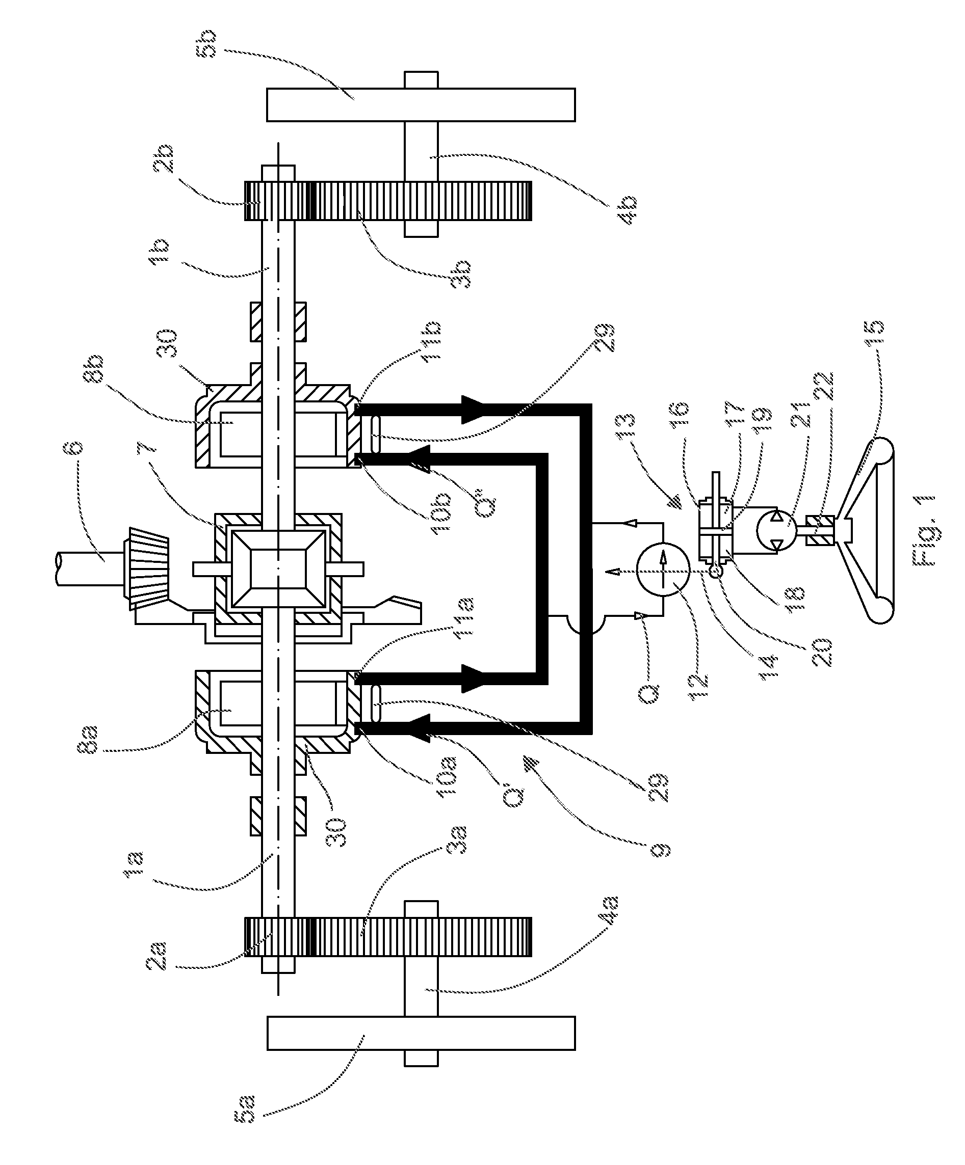
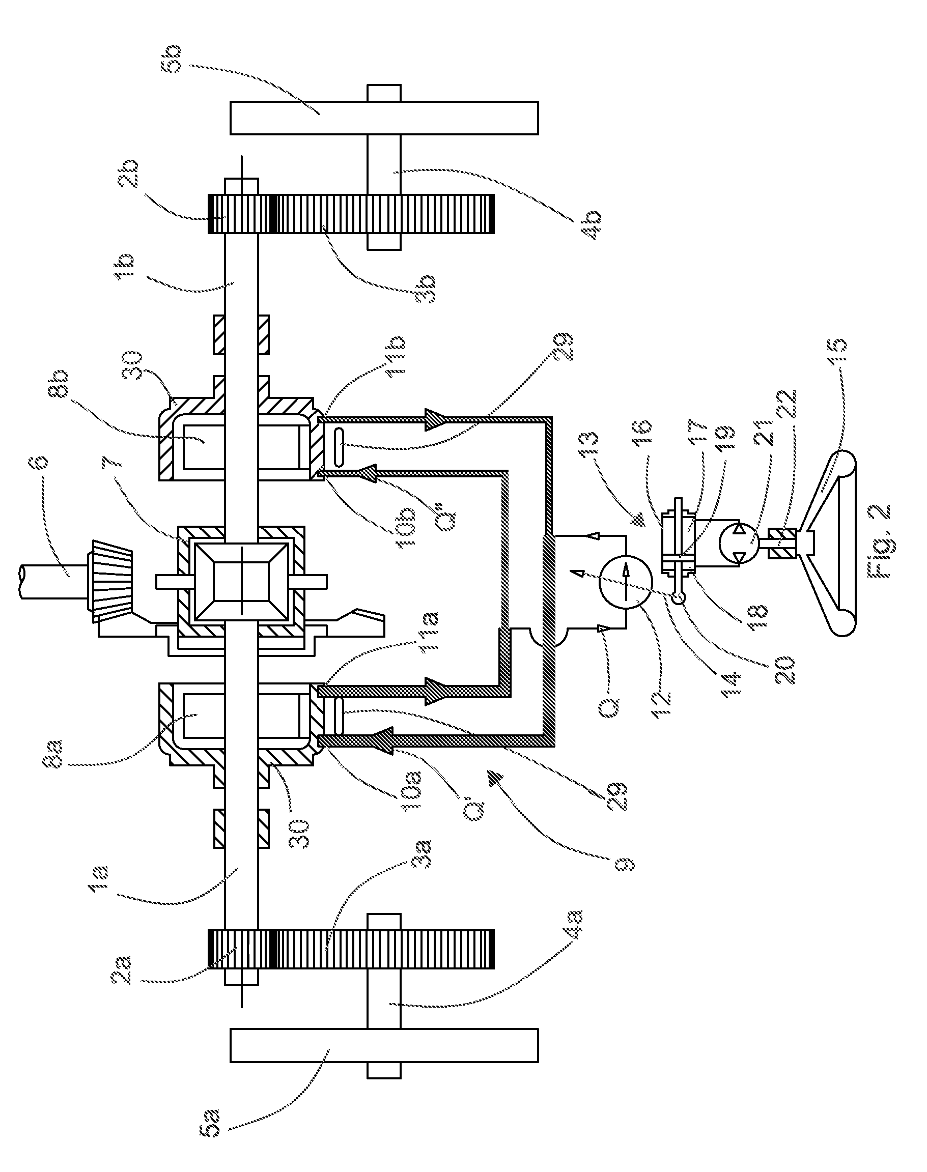
[0015]FIGS. 1 and 2 show a steering system for a vehicle, in particular a wheeled tractor or a crawler tractor, according to the invention comprising a first axle shaft 1a driving a first pinion 2a meshing with a first spur gear 3a connected to the shaft 4a of a first wheel 5a of a vehicle, or a first drive wheel of a first endless track, a second axle shaft 1b driving a second pinion 2b meshing with a second spur gear 3b connected to the shaft 4b of a second wheel 5b of the vehicle. The first axle shaft 1a and the second axle shaft 1b are driven by a power shaft 6 powered by an engine of the vehicle. Between the power shaft 6, the first axle shaft 1a and the second axle shafts 1b a differential gearing 7 is interposed that transmit motion from the power shaft 6 to the first axle shaft 1a and the second axle shaft 1b.

[0016]The first axle shaft 1a is associated with a first hydraulic unit 8a the rotor of which is connected to the first axle shaft 1a and the second axle shaft 1b is a...

second embodiment

[0030]FIG. 3 illustrates a steering system according to the invention in which the control device 14 of the control pump 12 is piloted by a lever 23 the ends of which are connected to respective piston rods 24 and 25 of a first hydraulic cylinder 26 and a second hydraulic cylinder 27, respectively, that are fed by the steering pump 21 driven by the steering column 22 of the steering wheel 15 of the vehicle.

[0031]When the steering wheel 15 is rotated in a first direction, or in a second direction opposite to the first direction, the steering pump 21 displaces a quantity of hydraulic fluid from the first hydraulic cylinder 26 to the second hydraulic cylinder 27, or viceversa, causing displacement of the piston rods 24 and 25 in opposite directions, which causes a rotation of the lever 23 and a consequent displacement of the control device 14 of the control pump 12 and a variation of the flow rate Q of the control pump and the flow rates Q′ of the first hydraulic unit 8a and Q″ of the ...

third embodiment

[0032]FIG. 4 illustrates a system according to the invention wherein the control device 14 of the control pump 12 is driven by a flexible cable 28 connected to the steering column 21 of the steering wheel 15 of the vehicle.

[0033]Alternatively, the control device 14 of the control pump 12 may be driven by a tie-rod connected to the steering wheel 15 of the vehicle.


PUM


Abstract

A steering system for a vehicle wherein the first and second axle shafts are driven by a power shaft powered by an engine. A differential gear is interposed between the power shaft and the first and second axle shafts. The steering system has a first hydraulic unit associated with the first axle shaft, a second hydraulic unit associated with the second axle shaft, a hydraulic circuit connecting an input of the first hydraulic unit to an output of the second hydraulic unit and an output of the first hydraulic unit to an input of said second hydraulic unit. A control unit is connected to the hydraulic circuit for varying a flow rate of hydraulic fluid in the first and second hydraulic units and an actuator associated with the control unit for controlling said control unit. The actuator is responsive to rotation of a steering wheel.

Description

[0001]The present invention relates to a steering control system, particularly a hydraulic steering control system for crawlers and wheeled tractors.BACKGROUND[0002]Previous steering systems for land vehicles having a pair of tractor wheels or endless tracks were driven by respective axle shafts powered by a power shaft connected to an engine, a differential gear being interposed between the power shaft and the axle shaft. Each axle shaft is associated with a hydraulic unit that may act both as a hydraulic motor or a hydraulic pump. The two hydraulic units are connected together by a hydraulic circuit that connects the input of a unit to the output of the other unit. A hydraulic pump having an adjustable flow rate is connected to the hydraulic circuit for varying the flow rate of a hydraulic fluid fed to the hydraulic unit, in order to have different speed of rotation of the two hydraulic units and, consequently different speed of rotation of the axle shafts driving the tractor whee...

Claims


Application Information

Patent Timeline
Patent Type & Authority Patents(United States)
IPC IPC(8): B62D11/18
CPCB62D11/18B62D11/183
Inventor BORDINI, GIORGIO
Owner BLUE LEAF I P INC
Why Eureka
Try Eureka