Multi-axial orthopedic device and system

a multi-axial, orthopedic technology, applied in the field of implants, can solve the problems of longer surgery duration

Active Publication Date: 2011-09-20
WARSAW ORTHOPEDIC INC
View PDF112 Cites 152 Cited by
  • Summary
  • Abstract
  • Description
  • Claims
  • Application Information

AI Technical Summary

Problems solved by technology

While useful in certain circumstances, in some therapeutic situations such an inflexible device is impractical, or can lead to a longer duration of surgery.

Method used


Image

  • Multi-axial orthopedic device and system
  • Multi-axial orthopedic device and system
  • Multi-axial orthopedic device and system

Examples


Embodiment Construction

[0026]For the purpose of promoting an understanding of the principles of the invention, reference will now be made to the embodiments illustrated in the drawings and specific language will be used to describe the same. It will nevertheless be understood that no limitation of the scope of the invention is thereby intended, such alterations and further modifications in the illustrated device, and such further applications of the principles of the invention as illustrated therein, being contemplated as would normally occur to one skilled in the art to which the invention relates.

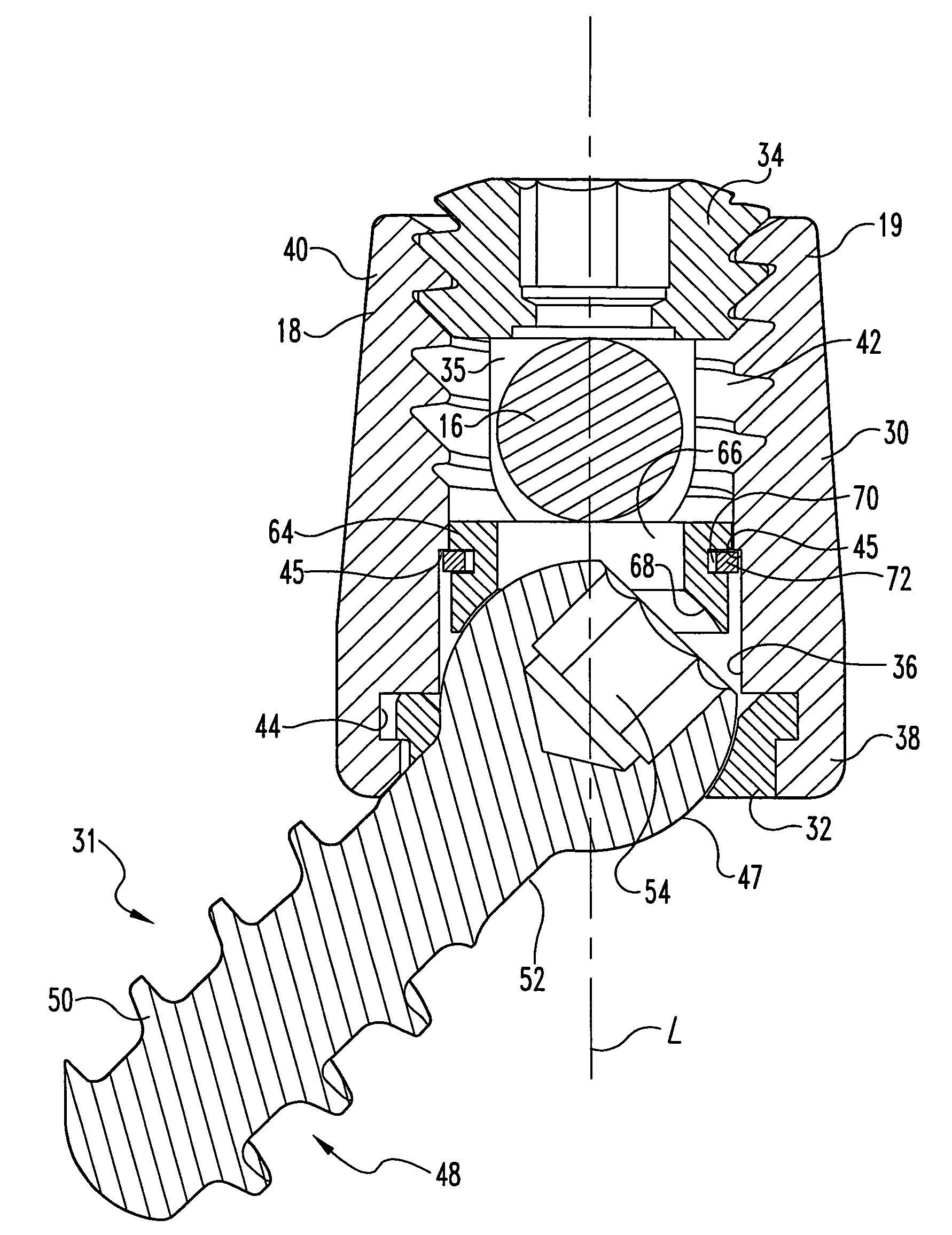
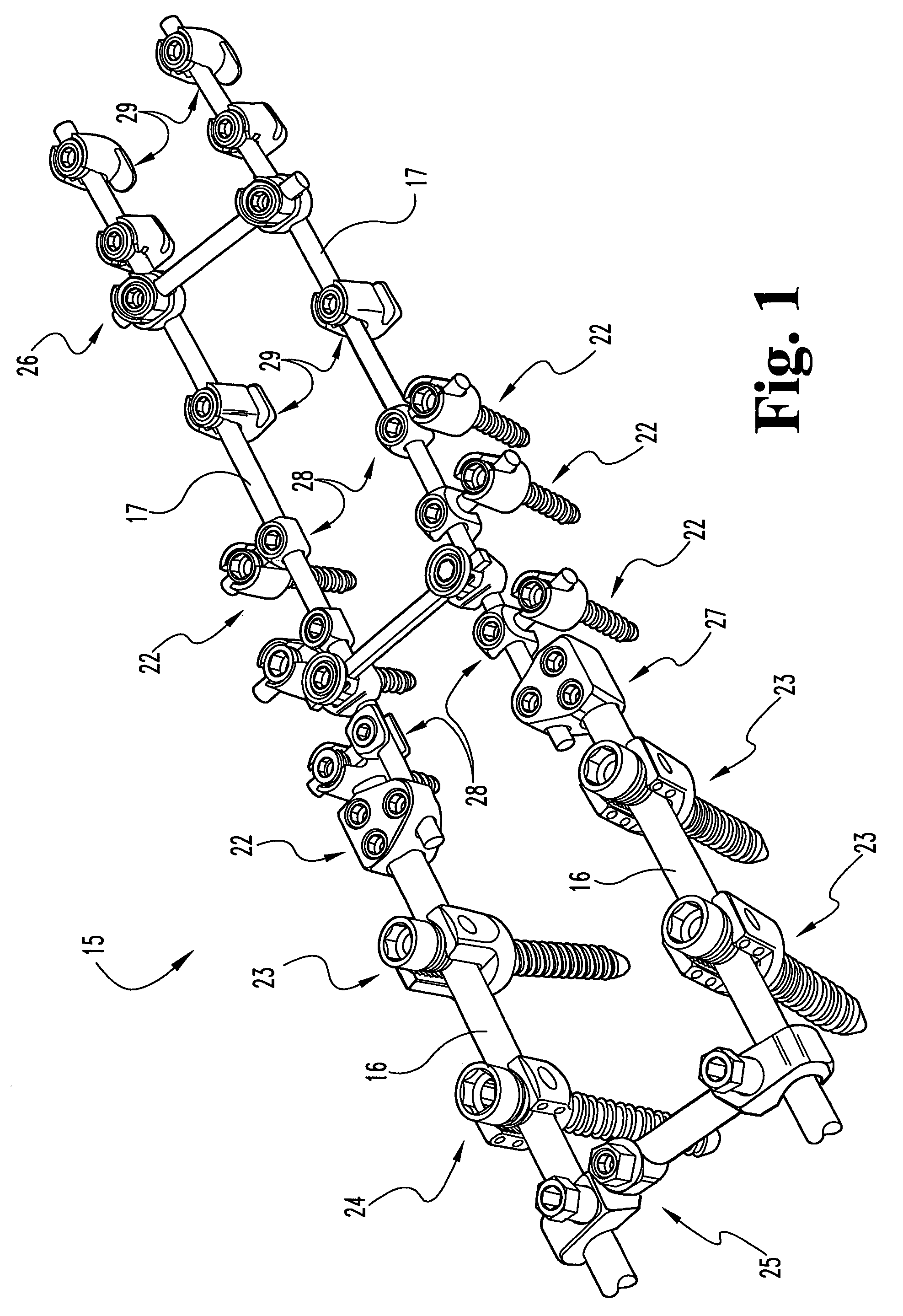
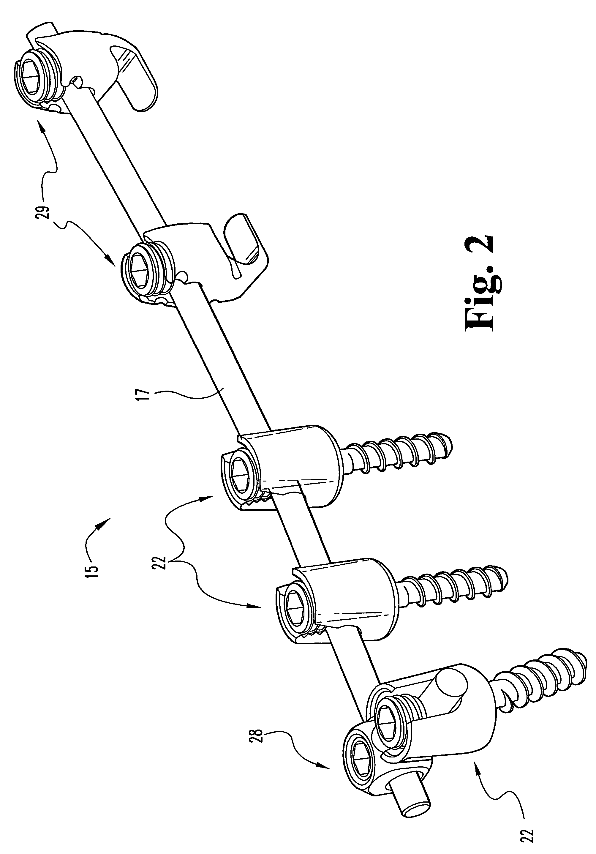
[0027]Referring generally to FIGS. 1-2, embodiments of a system 15 for orthopedic implantation are shown. Among the possible implants that can be a part of system 15 are longitudinal members such as rods 16, 17, bone attachment members such as screws 22, 23, 24, connectors such as cross connectors 25, 26, longitudinal connector 27, lateral connector 28, hooks 29, and other devices. It will be understood that ot...


PUM


Abstract

Embodiments of an orthopedic implant device and system, and methods for implanting them, are disclosed. The implant may include a receiver member having a channel for accommodating an elongated rod or other longitudinal member, a bone anchoring member such as a screw or hook, and a base member rotatable with respect to the receiver member for retaining the bone anchoring member in the receiver member. The base member is configured to allow at least two different degrees of maximum angulation of the bone anchoring member with respect to the receiver member. The number and relative direction of such angulations are independent of the orientation of the channel or other part of the receiving member.

Description

[0001]This application claims the benefit of U.S. Provisional Patent Application Ser. No. 60 / 496,536, filed Aug. 20, 2003.FIELD OF THE INVENTION[0002]The disclosed subject matter generally relates to implants used for correction of orthopedic injuries or deformities, and more specifically, but not exclusively, concerns apparatuses and methods for fixing a portion of the spine to allow correction or healing thereof.BACKGROUND[0003]In the realm of neurologic, orthopedic and spinal surgery, it is well known to use implants to fix the position of bones. In this way, the healing of a broken bone can be promoted, and malformations or other injuries can be corrected. For example, in the field of spinal surgery, it is well known to place such implants into vertebrae for a number of reasons, including (a) to correct an abnormal curvature of the spine, including a scoliotic curvature, (b) to maintain appropriate spacing and provide support to broken or otherwise injured vertebrae, and (c) to ...

Claims


Application Information

Patent Timeline
Patent Type & Authority Patents(United States)
IPC IPC(8): A61B17/70A61B17/00A61B19/00
CPCA61B17/7037A61B17/7041A61B17/7038A61B17/7011A61B17/7032A61B2019/305A61B17/7049A61B2017/00867A61B2090/035
Inventor FARRIS, ROBERT A.POYNER, JEFFREY W.
Owner WARSAW ORTHOPEDIC INC
Why Eureka
Try Eureka