Weapon system and method for beam containment and beamwalk maintenance utilizing optical fibers

a technology of optical fiber and beam containment, applied in the field of weapons systems and methods, can solve the problems of residual jitter, beamwalk mirror system cannot handle large disturbance, and current state-of-the-art beamwalk maintenance system based on active beamwalk mirrors suffer from several shortcomings

Active Publication Date: 2011-09-20
LOCKHEED MARTIN CORP
View PDF8 Cites 15 Cited by
  • Summary
  • Abstract
  • Description
  • Claims
  • Application Information

AI Technical Summary

Problems solved by technology

Although effective within their operational parameters, the current state-of-the-art beamwalk maintenance systems based on active beamwalk mirrors suffer from several shortcomings.
One of the problems is that the beamwalk mirror systems cannot handle large disturbances due to the limited range of movements of the mirrors and limited range of alignment operation that can be accomplished with a system of mirrors.
Another problem is what is known as residual jitter.
Although the feedback control systems for the beamwalk mirrors are driven by light (laser) and electronics, the system has finite, nonzero response time.
This means that small beamwalks that occur before the mirror systems have a chance to respond cannot be corrected, and, as a result, beamwalk mirror systems have inherently uncorrectable residual jitter corresponding to their system response time.
Other problems are related to the complexity of the active beamwalk mirror systems.
As described above, the active mirror based beamwalk maintenance systems are delicate systems with a large number of parts.
As well known in system engineering arts, the larger the number of parts, the greater the frequency of system failures, resulting from the failures of one or more parts.
Such comparatively high failure rate is particularly problematic for laser systems deployed in difficult-to-service environments, such as the Space Based Laser (SBL).

Method used


Image

  • Weapon system and method for beam containment and beamwalk maintenance utilizing optical fibers
  • Weapon system and method for beam containment and beamwalk maintenance utilizing optical fibers
  • Weapon system and method for beam containment and beamwalk maintenance utilizing optical fibers

Examples


Embodiment Construction

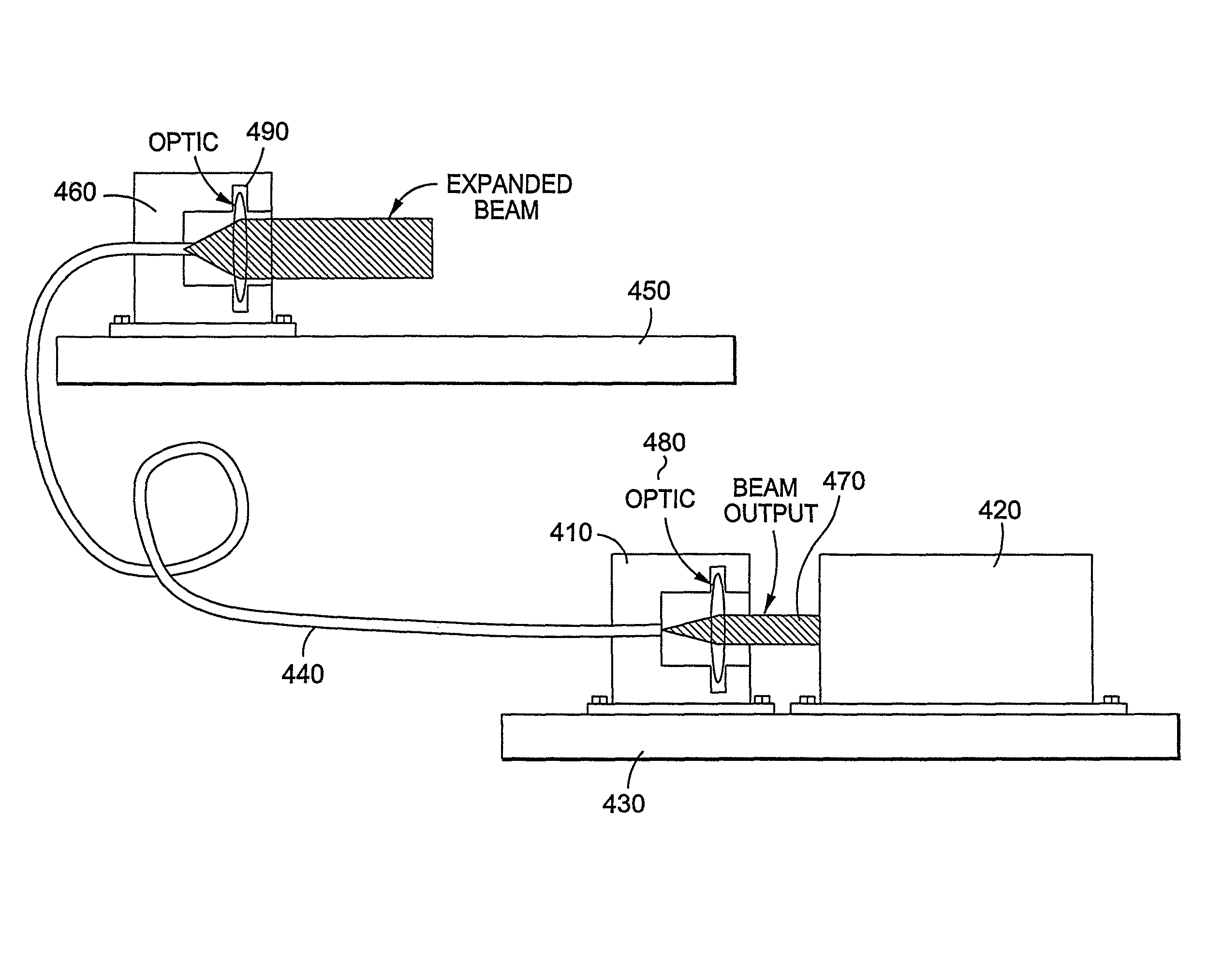
[0029]According to various aspects of the present invention, a beam containment and beamwalk maintenance system utilizing optical fibers provides several advantages over the existing mirror based systems. First, a system of the present invention greatly reduces complexity by eliminating the beamwalk mirrors, the processors, the control circuitry, the servo mechanism, the beamwalk laser source, and the beam transport tube. In addition, with a sufficiently long and loosely strung fiber between the benches, bench motion of much higher magnitude is tolerated than would be allowable with the old, beamwalk mirror pair and beam tube containment system.

[0030]According to one aspect of the invention, a system of the present invention eliminates the control feedback loop mechanism of the existing state-of-the-art systems. Since the optical fibers offer effectively instantaneous temporal response, the residual beam jitter is effectively eliminated. The present invention also provides a virtual...


PUM


Abstract

A weapon system includes a weapon system illuminator laser system and one or more optical fibers. The weapon system illuminator laser system can produce one or more illuminator laser beams to illuminate at least one object outside the weapon system without destroying the object. The weapon system illuminator laser system is located at a first location within the weapon system. The object, or a second object associated with the object, is to be destroyed or damaged by energy. The one or more optical fibers are configured to transport the one or more illuminator laser beams from the first location to a second location within the weapon system. The one or more optical fibers can provide beam containment and beamwalk maintenance in the presence of mechanical or thermal disturbances. The one or more optical fibers and the weapon system illuminator laser system can withstand mechanical or thermal disturbances.

Description

CROSS-REFERENCE TO RELATED APPLICATION[0001]This is a continuation-in-part of U.S. patent application Ser. No. 10 / 851,168 entitled “SYSTEM AND APPARATUS FOR BEAM CONTAINMENT AND BEAM WALK MAINTENANCE FOR HIGH POWER LASER BEAMS UTILIZING OPTICAL FIBERS,” filed on May 24, 2004, which is hereby incorporated by reference in its entirety for all purposes.STATEMENT AS TO RIGHTS TO INVENTIONS MADE UNDER FEDERALLY SPONSORED RESEARCH OR DEVELOPMENT[0002]Not Applicable.BACKGROUND OF THE INVENTION[0003]1. Field[0004]The present invention relates generally to weapon systems and methods, and more particularly to weapon systems and methods for beam containment and beamwalk maintenance utilizing optical fibers.[0005]2. Background[0006]Currently, the state-of-the-art approach to the problem of line-of-sight beam alignment for airborne laser systems is various active beamwalk alignment or maintenance systems that comprise a set of active beamwalk mirrors controlled by complicated electro-servo mecha...

Claims


Application Information

Patent Timeline
Patent Type & Authority Patents(United States)
IPC IPC(8): H01S3/30
CPCF41H13/005G01S7/4814G01S17/66G02B6/02328G02B6/3616G02B6/4206G02B6/4296
Inventor BILLMAN, KENNETH W.
Owner LOCKHEED MARTIN CORP
Why Eureka
Try Eureka