Interfering signal characterizing quantity storing method and device, interfering signal characterizing quantity acquiring method and device, and interfering signal suppressing method and device
a technology of interfering signal and quantity, applied in the field of interfering signal suppressing technique, can solve the problem of high probability of demodulation error of desired signal due to the effect of interfering signal, and achieve the effect of high accuracy
- Summary
- Abstract
- Description
- Claims
- Application Information
AI Technical Summary
Benefits of technology
Problems solved by technology
Method used
Image
Examples
first embodiment
Example 1
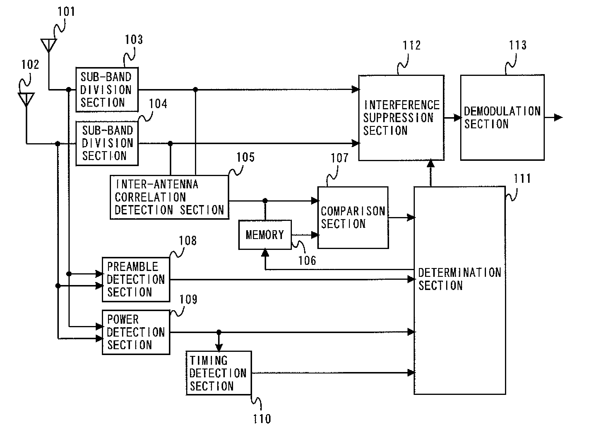
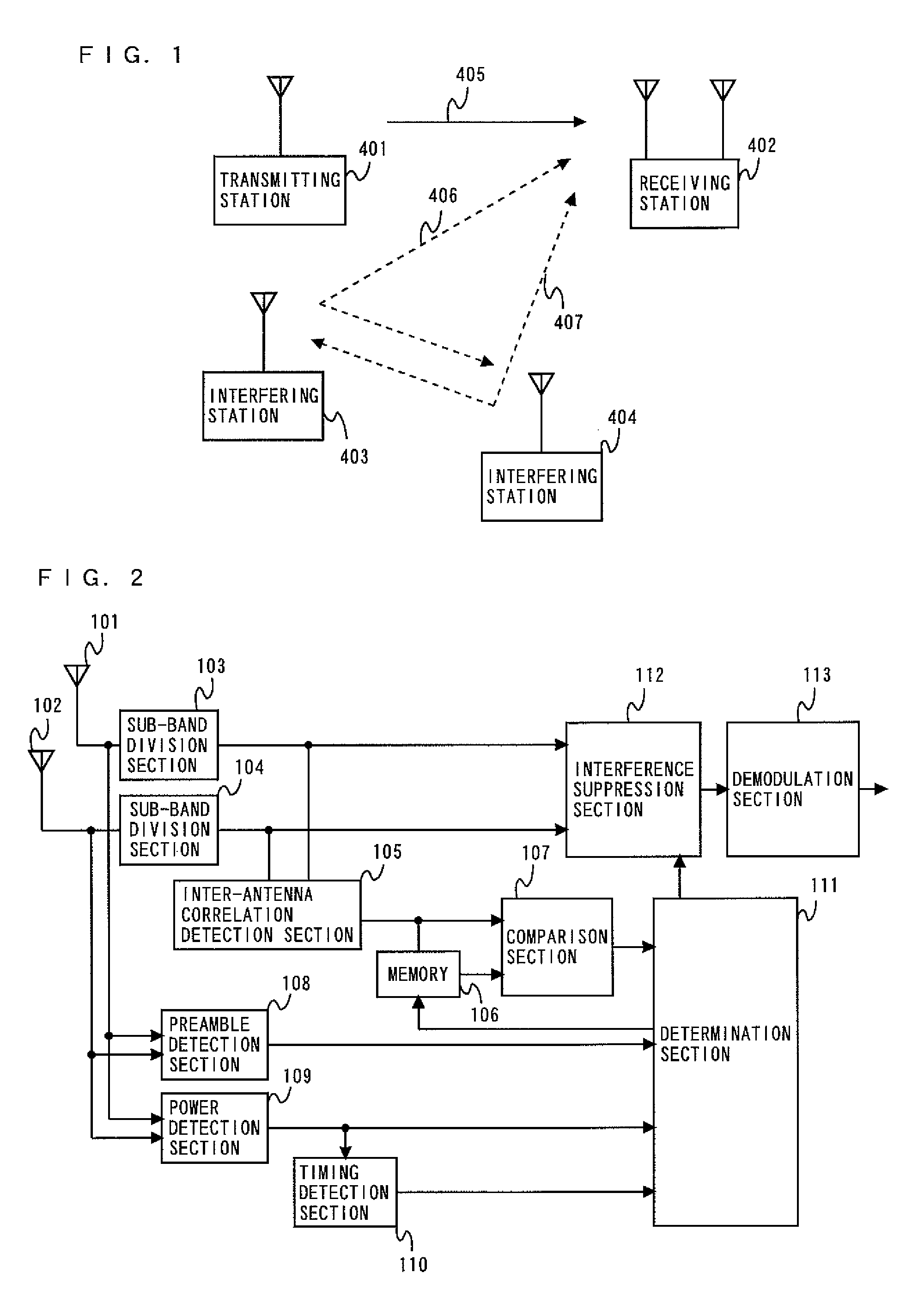
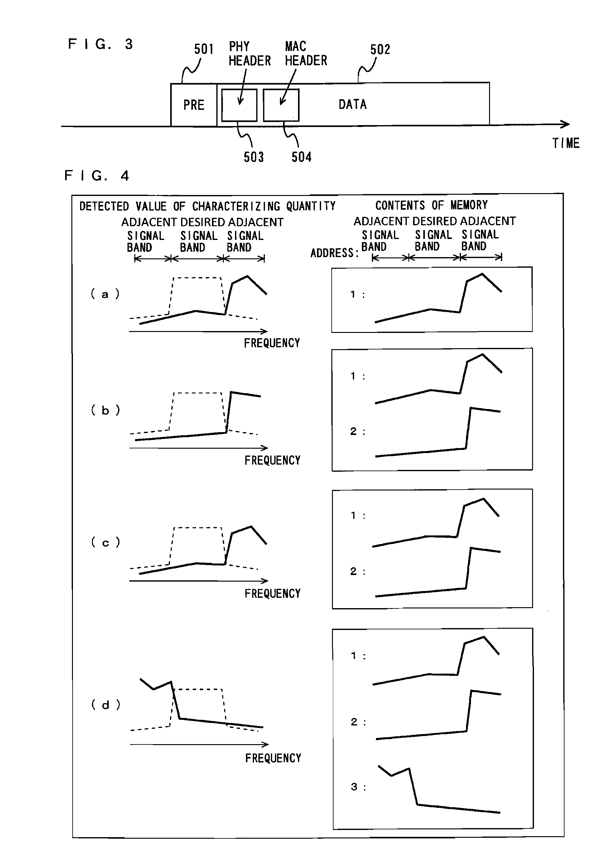
[0200]An exemplary overall configuration and an exemplary overall operation of a radio communication system including an interfering signal suppressing device according to an example 1 of a first embodiment will be described. The interfering signal suppressing device according to the example 1 can be regarded as a receiving station in the radio communication system. Hereinafter, the interfering signal suppressing device according to the example 1 is referred to as a receiving station according to need. FIG. 1 is a view showing an example of the radio communication system including the interfering signal suppressing device according to the example 1. As shown in FIG. 1, the radio communication system including the interfering signal suppressing device 402 (the receiving station 402) according to the example 1 comprises a transmitting station 401, the receiving station 402, and interfering stations 403 and 404. The transmitting station 401 converts into a radio signal 405 tra...
second embodiment
Example 1
[0284]FIG. 15 is a block diagram showing a configuration of an interfering signal suppressing device 2120 according to an example 1 of the second embodiment. The interfering signal suppressing device according to the example 1 is regarded as a receiving station in the radio communication system. In the following description, the interfering signal suppressing device is referred to as a receiving station according to need.
[0285]As shown in FIG. 15, the interfering signal suppressing device (the receiving station) 2120 includes two antennas 2101 and 2102, an inter-received-signal characterizing quantity extraction section 2103, a storage section 2104, a storage section 2104, a comparison section 2105, a determination section 2106, an interfering signal suppression section 2107, and a demodulation section 2108.
[0286]The antennas 2101 and 2102 shown in FIG. 15 output received signals to the inter-received-signal characterizing quantity extraction section 2103 and the interferin...
third embodiment
Example 1
[0387]An exemplary overall configuration and an exemplary overall operation of a radio communication system including an interfering signal suppressing device according to an example 1 of the third embodiment will be described. The interfering signal suppressing device according to the example 1 is regarded as a receiving station in the radio communication system. In the following description, the interfering signal suppressing device is referred to as a receiving station according to need.
[0388]FIG. 27 is a view showing an example of the radio communication system including the interfering signal suppressing device according to the example 1. As shown in FIG. 27, the radio communication system including the interfering signal suppressing device (a receiving station) 3302 according to the example 1 comprises a transmitting station 3301, the receiving station 3302, a radio station A 3303, a radio station B 3304, a radio station C 3305, and a radio station D 3306. The radio s...
PUM
 Abstract
Description
Claims
Application Information
 - R&D
- Intellectual Property
- Life Sciences
- Materials
- Tech Scout
- Unparalleled Data Quality
- Higher Quality Content
- 60% Fewer Hallucinations
Browse by: Latest US Patents, China's latest patents, Technical Efficacy Thesaurus, Application Domain, Technology Topic, Popular Technical Reports.
© 2025 PatSnap. All rights reserved.Legal|Privacy policy|Modern Slavery Act Transparency Statement|Sitemap|About US| Contact US: help@patsnap.com


