
Image capturing module

a technology of image capturing and module, which is applied in the field of image capturing modules, can solve the problems of increasing the number of parts, increasing the cost of the motor, and the volume of the camera module implemented in the mobile phone, so as to reduce the volume of the camera module and reduce the assembly tolerance of each par

Inactive Publication Date: 2011-09-27
COMPACT LENS TECH LLC
View PDF10 Cites 4 Cited by
  • Summary
  • Abstract
  • Description
  • Claims
  • Application Information

AI Technical Summary

Benefits of technology

"The present invention provides an image capturing module that can be smaller and more tolerant to assembly variations. The module includes a lens assembly, a lens driving unit, a piezoelectric motor, a pressurizing member, and a plurality of ball assemblies. The plurality of ball assemblies prevents tilting of the lens assembly and ensures stability during movement. The guiding protrusions and guiding holes guide the lens assembly along the optical axis. The piezoelectric motor moves the lens assembly along the optical axis using a frictional force with a drive shaft. The module supporting unit includes an image sensor that converts light into an electric signal."

Problems solved by technology

Thus, camera modules implemented in mobile phones may have a large volume and thickness.
However, in a step motor, since the size of an operating module increases due to increasing implementation of application parts, such as a reduction gear and connection parts, and an increasing size of the motor itself, and a cost of the motor increases due to the increasing implementation of the parts, a lens driving method using an ultrasonic motor such as a piezoelectric motor is widely used in camera modules employed in small digital cameras or mobile phones due to current light-weighted and minimized products.
However, in this case, the number of parts increases and an assembly tolerance of each part may be hardly reduced.

Method used


Image

  • Image capturing module
  • Image capturing module
  • Image capturing module

Examples


Embodiment Construction

[0031]The present invention will now be described more fully with reference to the accompanying drawings, in which exemplary embodiments of the invention are shown.

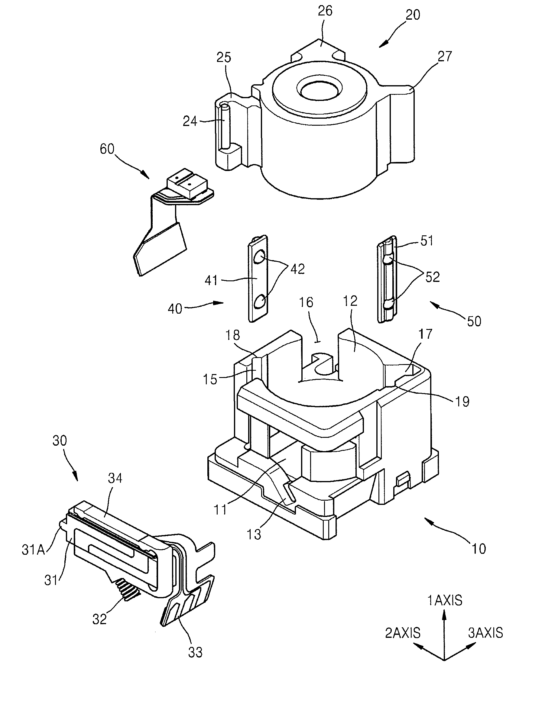
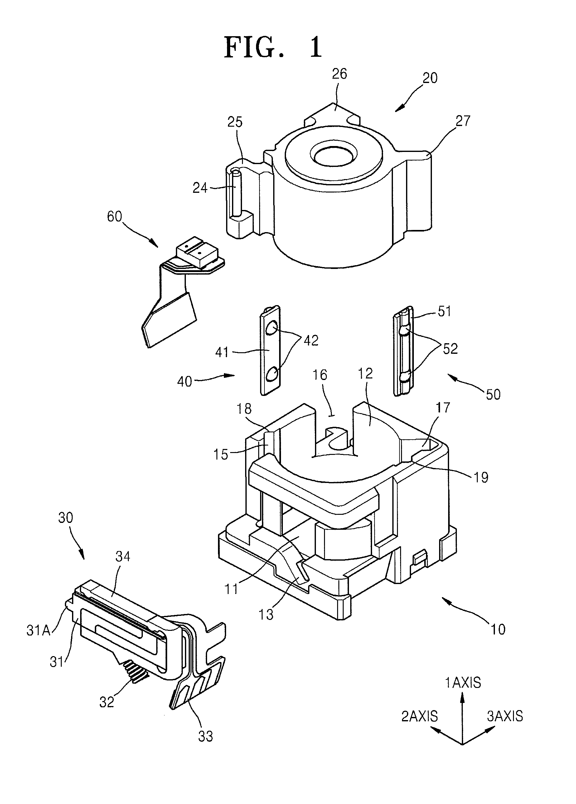
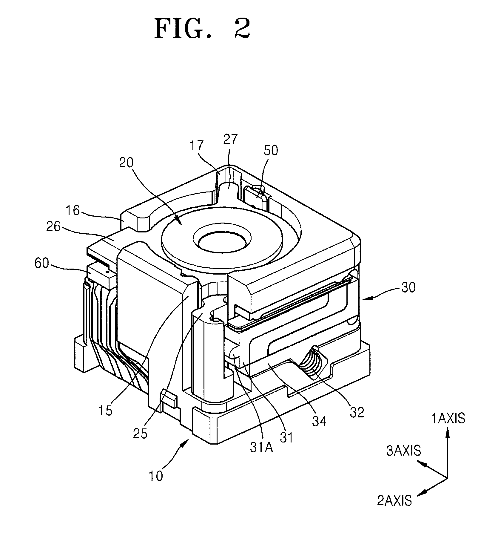
[0032]FIG. 1 is an exploded perspective view of an image capturing module according to an exemplary embodiment of the present invention; FIG. 2 is a combined perspective view of the image capturing module of FIG. 1; FIG. 3 is a plan view of the image capturing module of FIG. 2; and FIG. 4 is a front view of the image capturing module of FIG. 2.

[0033]Referring to FIGS. 1 through 4, the image capturing module according to an exemplary embodiment of the present embodiment includes a module supporting unit 10, a lens assembly 20, a lens driving unit 30, a first ball assembly 40, a second ball assembly 50, and a location sensor 60.

[0034]The module supporting unit 10 may include an image sensor 11 that may be a charge-coupled device (CCD) sensor or a complementary metal oxide semiconductor (CMOS) sensor. The module supporting u...


PUM


Abstract

An image capturing module is provided. The image capturing module includes: a lens assembly supporting at least one lens, moving along an optical axis of light indicating an image of a subject, and comprising guiding protrusions for guiding the moving the optical axis; a module supporting unit comprising guiding holes to which the guiding protrusions are inserted to guide the lens assembly; a lens driving unit comprising a winding vibration type piezoelectric motor and a piezoelectric motor supporting member, wherein the winding vibration type piezoelectric motor is disposed on the module supporting unit and moves the lens assembly along the optical axis and the piezoelectric motor supporting member supports the winding vibration type piezoelectric motor; a pressurizing member interposed between the piezoelectric motor supporting member and the module supporting unit; and a plurality of ball assemblies interposed between the module supporting unit and the lens assembly.

Description

CROSS-REFERENCE TO RELATED PATENT APPLICATION[0001]This application claims priority from Korean Patent Application No. 10-2008-0058362, filed on Jun. 20, 2008, in the Korean Intellectual Property Office, the disclosure of which is incorporated herein in its entirety by reference.BACKGROUND OF THE INVENTION[0002]1. Field of the Invention[0003]Apparatuses consistent with the present invention relate to an image capturing module, and more particularly, to an image capturing module using a winding vibration type piezoelectric motor having a thin small volume and capable of performing a zoom or automatic focusing (AF) function in a digital camera.[0004]2. Description of the Related Art[0005]Currently, camera modules having an automatic focusing (AF) function or a zoom adjusting function implemented in mobile electronic devices, such as mobile phones, are being widely used. As the thickness of a camera module implemented in a mobile phone increases, the thickness of the mobile phone also ...

Claims


Application Information

Patent Timeline
Patent Type & Authority Patents(United States)
IPC IPC(8): G02B7/02G02B15/14
CPCG02B7/102H04N23/58H04N23/57H04N23/55
Inventor KIM, DAE-KYUNGLEE, IN-HWANJUNG, TAE-HOON
Owner COMPACT LENS TECH LLC
Learn More