Fuel element for a boiling water reactor

Inactive Publication Date: 2011-09-27
AREVA GMBH
View PDF8 Cites 0 Cited by
  • Summary
  • Abstract
  • Description
  • Claims
  • Application Information

AI Technical Summary

Benefits of technology

[0003]This object is achieved by a fuel assembly with a skirt that is integrally formed on the underside of the stopper, which is arranged at the lower end of the water channel, and extends, in a rotationally-fixed manner, into an opening passing through the sieve plate. Furthermore, a bush is provided, having a first and a second longitudinal section, wherein the second longitudinal section projects from the underside of the sieve plate into the opening of the latter in a rotationally-fixed manner and wherein the outer side of a radial shoulder located between the two longitudinal sections bears against the underside of the sieve plate. Finally, the threaded bolt of a screw passes through the bush, which engages in a thread of the bore of the stopper. It is an advantage of the described connection that it completely dispenses with the complicated production of welded or soldered seams and therefore has a high fatigue strength, on the one hand, and low assembly outlay, on the other hand. The rotationally-fixed engagement of the skirt in the opening of the sieve plate rules out a change in the rotational position between water channel and fuel assembly foot. The rotational connection is preferably achieved in that the skirt has a polygonal contour and a region (which surrounds the skirt) of the screen-plate opening has a cross-sectional area complementary thereto.

Problems solved by technology

When applying force in the axial direction, there is a risk that the webs will flex and the screw-connection will lose strength as a result.
The proposed refinement, however, prevents this effectively.

Method used


Image

  • Fuel element for a boiling water reactor
  • Fuel element for a boiling water reactor
  • Fuel element for a boiling water reactor

Examples


Embodiment Construction

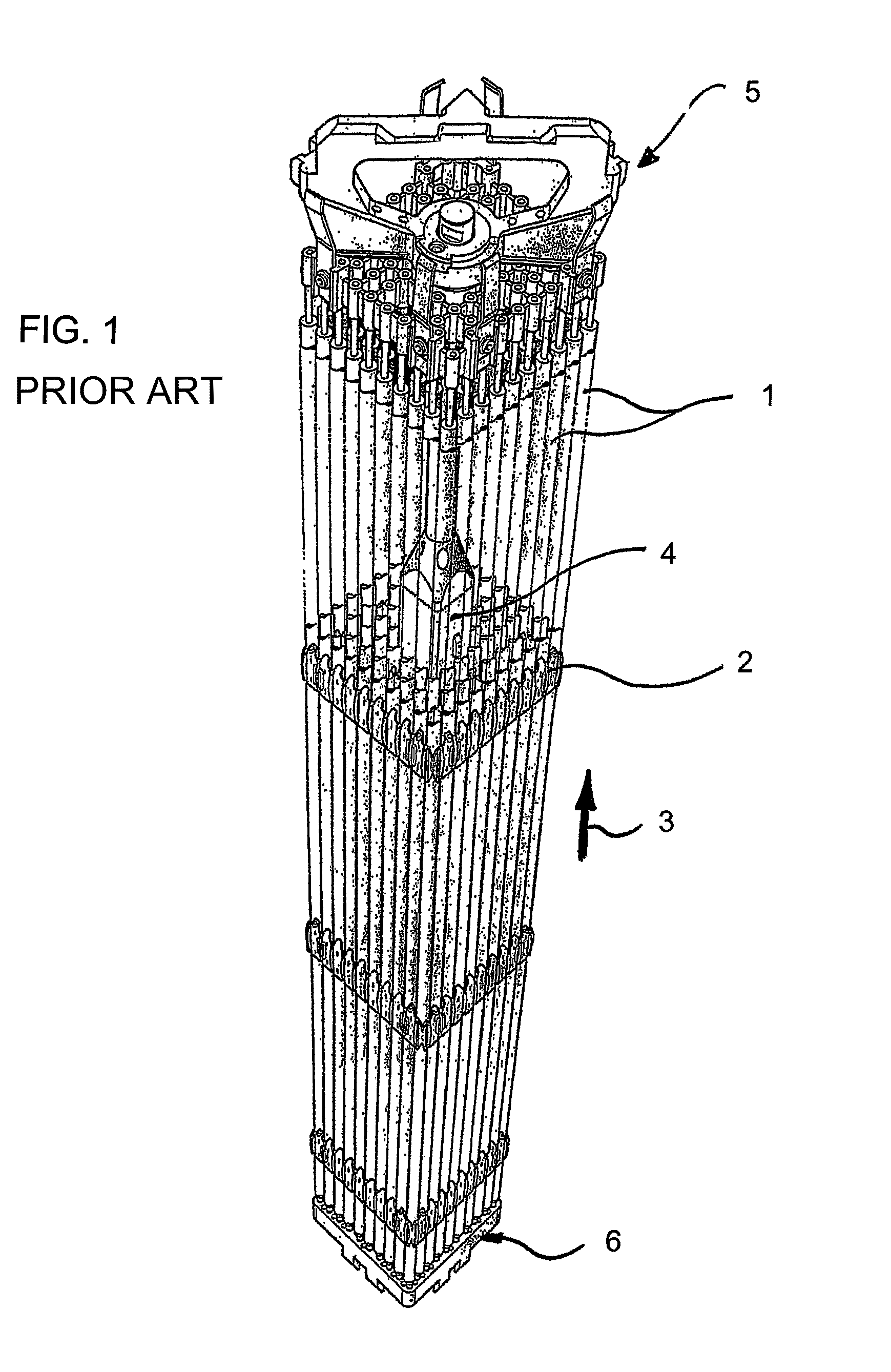
[0017]FIG. 1 shows a fuel assembly of a boiling water reactor comprising a bundle of a multiplicity of fuel rods 1 filled with nuclear fuel. The fuel rods are attached laterally by a plurality of spacers 2 arranged in different axial positions. A water channel 4 extends in the axial direction 3 approximately centrally in the fuel-rod bundle. A fuel assembly top fitting 5 is arranged at the upper side of the fuel assembly and a fuel assembly foot 6 is arranged at the lower side.

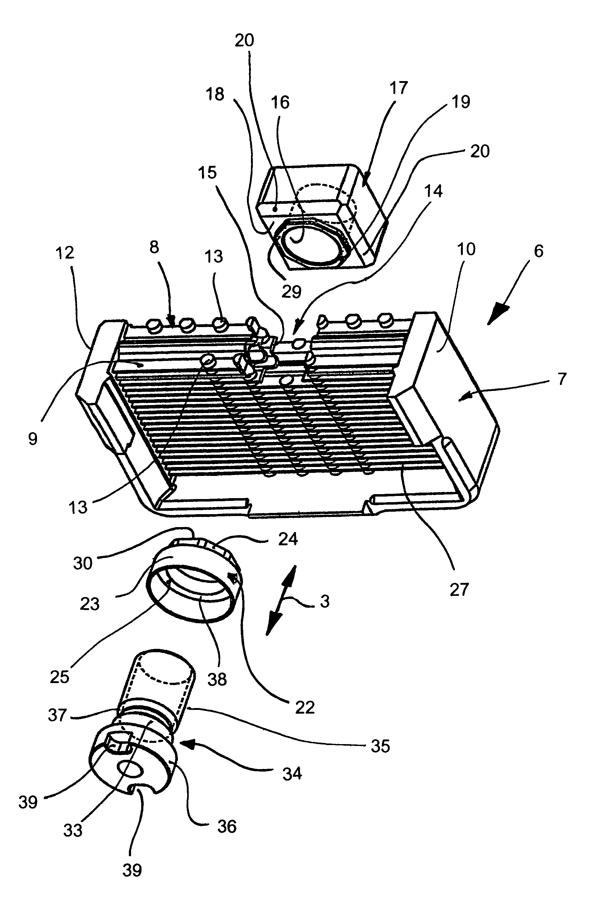
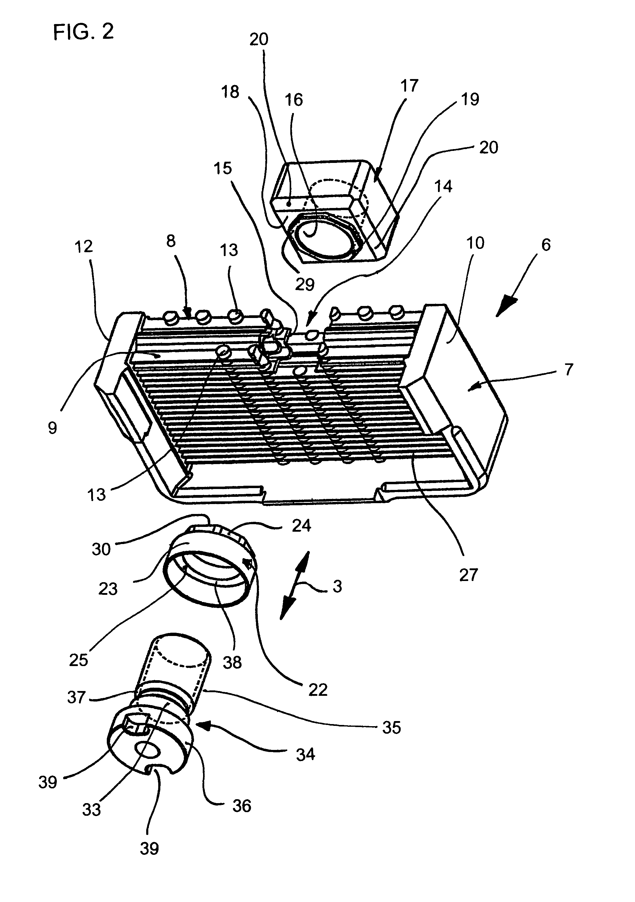
[0018]The fuel assembly foot 6 substantially comprises, as can be seen in FIG. 2, for example, a frame part 7 and a sieve plate 8. The sieve plate 8 is formed by a multiplicity of webs 9, which extend between two opposite walls 10, 12 of the frame part 7. The webs 9 are arranged, at a distance from one another, transversely with respect to their longitudinal direction. They are connected to one another in the same direction by struts 13 integrally formed thereon.

[0019]An opening 14 passes through the sieve pla...


PUM


Abstract

A fuel assembly for a boiling-water reactor has a water channel and a fuel assembly base, made from a sieve plate and a frame section enclosing the same. The water channel supports a plug with a bore running therethrough, at the lower end thereof, to which the fuel assembly base is fixed. The fuel assembly further comprises an opening through the sieve plate, a skirt, formed on the underside of the plug, surrounding the bore, extending into the opening in the sieve plate, a bush, provided with a first and a second longitudinal section, whereby the first longitudinal section extends from the underside of the sieve plate into the opening in a rotationally-fixed manner and a radial shoulder is provided between the two sections which contacts the underside of the sieve plate. A threaded section of a screw extends through the bush which engages in a thread in the bore in the plug.

Description

BACKGROUND OF THE INVENTIONField of the Invention[0001]The invention relates to a fuel assembly for a boiling water reactor. A fuel assembly of this type comprises a bundle of fuel rods filled with nuclear fuel, which are held axially by a plurality of spacers. A water channel runs approximately centrally in the fuel-rod bundle, the lower end of the water channel carrying a stopper, through which a bore passes. The water channel is attached to the fuel assembly foot with the aid of said stopper. The fuel assembly foot itself, or at least part thereof, is formed by a frame part surrounding a sieve plate. In a fuel assembly known from EP 1 280 163 A1, the sieve plate includes a bore, into which a threaded sleeve is inserted from the underside of the sieve plate and soldered there. A soldering of this type requires an increased manufacturing outlay and is also problematic with respect to fatigue strength during use in a nuclear reactor.SUMMARY OF THE INVENTION[0002]It is an object of t...

Claims


Application Information

Patent Timeline
IPC IPC(8): G21C15/00G21C3/34G21C3/32G21C3/322G21C3/33
CPCG21C3/322G21C3/3305Y02E30/31Y02E30/38Y02E30/30
Inventor LIEBLER-RANZUS, MICHAELFRIEDRICH, ERHARD
Owner AREVA GMBH
Why Eureka
Try Eureka