Active feed forward amplifier

a technology of active feed and amplifier, applied in the direction of amplifier, amplifier modification to reduce noise influence, amplifier, etc., can solve the problems of inherently limited bandwidth of prior art feed forward amplifier, bulky and expensive amplifier, and inability to provide pure linear amplification of radio frequency amplifiers, etc., to achieve optimal spurious signal cancellation and ultra-compact size and broadband performan

Active Publication Date: 2011-10-04
VIASAT INC
View PDF38 Cites 15 Cited by
  • Summary
  • Abstract
  • Description
  • Claims
  • Application Information

AI Technical Summary

Benefits of technology

[0004]In an exemplary embodiment, a feed forward amplifier is implemented as a fully monolithic silicon germanium (SiGe) based architecture. The feed forward amplifier may be used in communication applications that require low intermodulation products. An exemplary embodiment of the feed forward amplifier replaces traditional distributed directional couplers, splitters, and delay lines. Moreover, an exemplary feed forward amplifier architecture combines active implementations of RF couplers, power splitters, and / or time delay elements in a novel fashion allowing for ultra-compact size and broadband performance. In an exemplary embodiment, the feed forward amplifier replaces the directional couplers with active splitters and active combiners. Similarly, the delay lines and amplitude adjustment elements are replaced by active vector generators. The vector generators adjust the gain and phase of the error signal and are software reconfigurable for optimal spurious signal cancellation.

Problems solved by technology

In general, radio frequency (RF) amplifiers do not provide pure linear amplification and produce undesired spurious or intermodulation products at the amplifier output.
However, these distributed components result in a bulky and expensive amplifier.
In general, the bandwidth of a prior art feed forward amplifier is inherently limited by a distributed solution of the multiple couplers.

Method used


Image

  • Active feed forward amplifier
  • Active feed forward amplifier
  • Active feed forward amplifier

Examples


Embodiment Construction

[0011]While exemplary embodiments are described herein in sufficient detail to enable those skilled in the art to practice the invention, it should be understood that other embodiments may be realized and that logical material, electrical, and mechanical changes may be made without departing from the spirit and scope of the invention. Thus, the following detailed description is presented for purposes of illustration only.

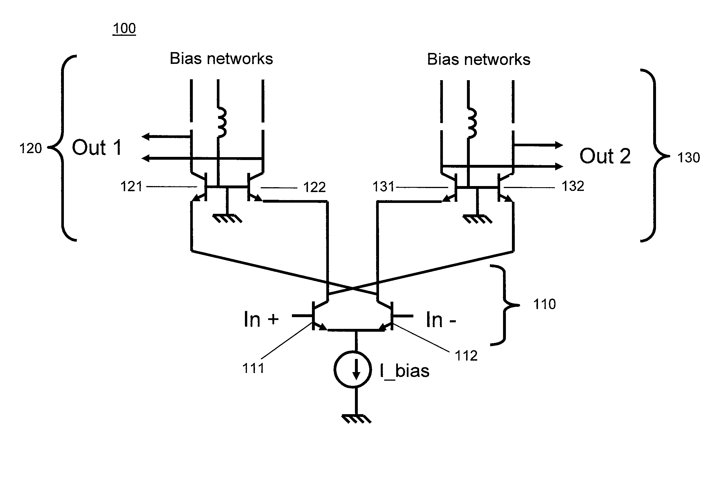
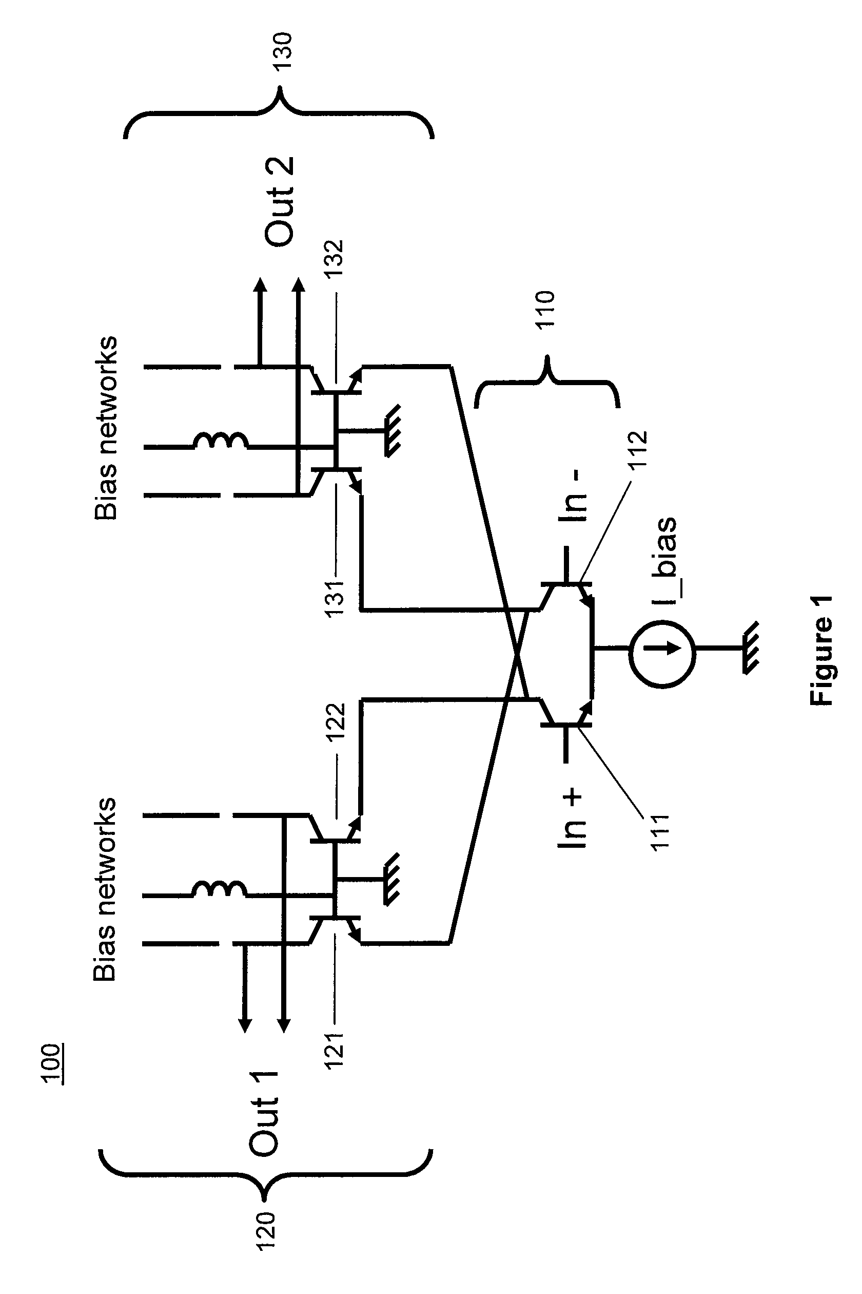
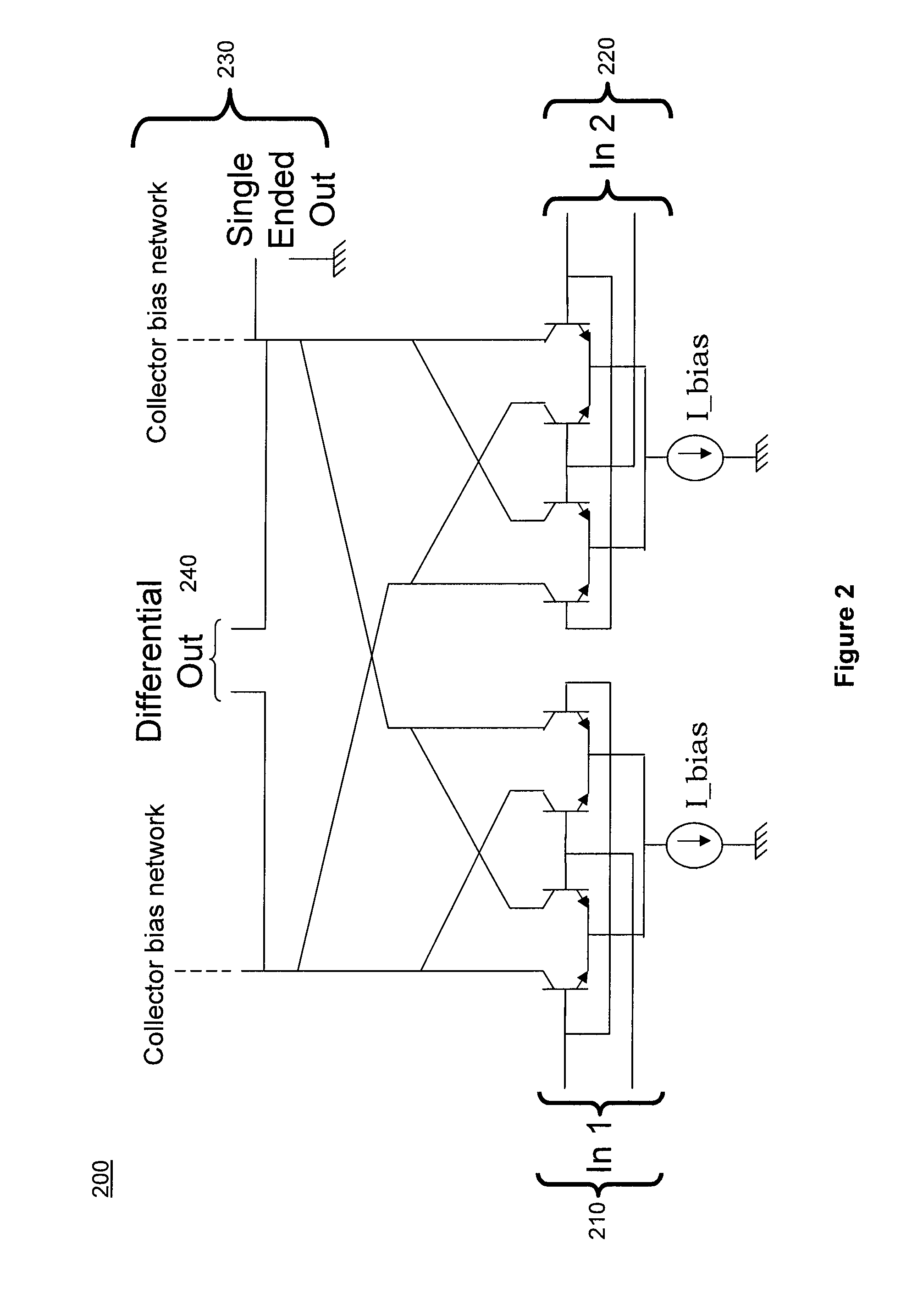
[0012]A feed forward amplifier corrects for the distortion injected by an amplifier using a forward loop. Specifically, the feed forward amplifier corrects the amplitude and phase distortion that results from the non-linear characteristics of an amplifier. In an exemplary embodiment, a feed forward amplifier comprises an error compensation loop that generates an error cancellation signal that is subtracted from the amplified and distorted main signal. In an exemplary embodiment, a feed forward amplifier is comprised of various components. The various components may ...


PUM


Abstract

An exemplary embodiment of the feed forward amplifier replaces traditional distributed directional couplers, splitters, and delay lines. Moreover, an exemplary feed forward amplifier architecture combines active implementations of RF couplers, power splitters, and / or time delay elements in a novel fashion allowing for ultra-compact size and broadband performance. In an exemplary embodiment, a feed forward amplifier has a main amplifier path and an error amplifier path. The feed forward amplifier comprises a main amplifier in the main amplifier path, and at least one active vector generator in the error amplifier path. The at least one active vector generator is configured to adjust the phase and amplitude of an error amplifier path signal and an error amplifier is configured to receive the adjusted error amplifier path signal. Furthermore, the adjusted error amplifier path signal and an amplified signal are combined to form the output signal of the feed forward amplifier.

Description

CROSS REFERENCE TO RELATED APPLICATIONS[0001]This application is a non-provisional of U.S. Provisional Application No. 61 / 237,967, entitled “ACTIVE BUTLER AND BLASS MATRICES,” which was filed on Aug. 28, 2009. This application is also a non-provisional of U.S. Provisional Application No. 61 / 259,375, entitled “ACTIVE HYBRIDS FOR ANTENNA SYSTEMS,” which was filed on Nov. 9, 2009. This application is a non-provisional of U.S. Provisional Application No. 61 / 234,513, entitled “ACTIVE FEED FORWARD AMPLIFIER,” which was filed on Aug. 17, 2009. This application is a non-provisional of U.S. Provisional Application No. 61 / 222,354, entitled “ACTIVE PHASED ARRAY ARCHITECTURE,” which was filed on Jul. 1, 2009. This application is a non-provisional of U.S. Provisional Application No. 61 / 168,913, entitled “ACTIVE COMPONENT PHASED ARRAY ANTENNA,” which was filed on Apr. 13, 2009. This application is also a non-provisional of U.S. Provisional Application No. 61 / 259,049, entitled “DYNAMIC REAL-TIME P...

Claims


Application Information

Patent Timeline
Patent Type & Authority Patents(United States)
IPC IPC(8): H03F1/00
CPCH01Q3/26H01Q3/36H01Q3/34G06G7/12H01Q15/242H03H11/36
Inventor CORMAN, DAVID W.
Owner VIASAT INC
Why Eureka
Try Eureka