System and method for detecting emplacement of improvised explosive devices

Active Publication Date: 2011-10-04
TEXTRON SYST
View PDF28 Cites 7 Cited by
  • Summary
  • Abstract
  • Description
  • Claims
  • Application Information

AI Technical Summary

Benefits of technology

[0006]In contrast to the conventional IED detection approach, embodiments of the invention are directed to techniques for detecting activity associated with placing an explosive device, such as an IED or landmine, within a particular geographic area. A detection system includes sensors and base station that detect and report on suspected IED emplacement activity within the area. When disposed within a geographic area, each sensor forms part of a wireless communications network which allows communication among neighboring sensors. As a sensor detects activity in its proximity, such as activity that indicates emplacement of an IED, the sensor transmits a reporting signal through the network to the base station. The neighboring sensors receive and transmit the reporting signal in a sequential manner toward the base station. Because the reporting signal takes multiple hops to the base station, each sensor transmits signals only to nearby neighboring and, therefore the sensors do not require large amounts of power to transmit the signal. Furthermore, the detection system allows detection of IED emplacement within the geographic area as the activity occurs. As a result, the base station can direct mobile response units to take immediate responsive action to

Problems solved by technology

However, these techniques suffer from a variety of deficiencies.
As a vehicle or personnel moves into the detection range of the motion sensor, the motion sensor transmits a signal to the IED, causing it to detonate.
Additionally, while the military has added or increased the amount of armor on military vehicles, detonation of larger IED's, or Explosively Formed Penetrator (EFP) devices

Method used


Image

  • System and method for detecting emplacement of improvised explosive devices
  • System and method for detecting emplacement of improvised explosive devices
  • System and method for detecting emplacement of improvised explosive devices

Examples


Embodiment Construction

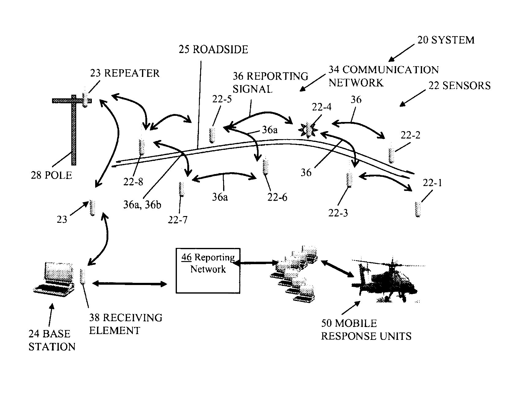
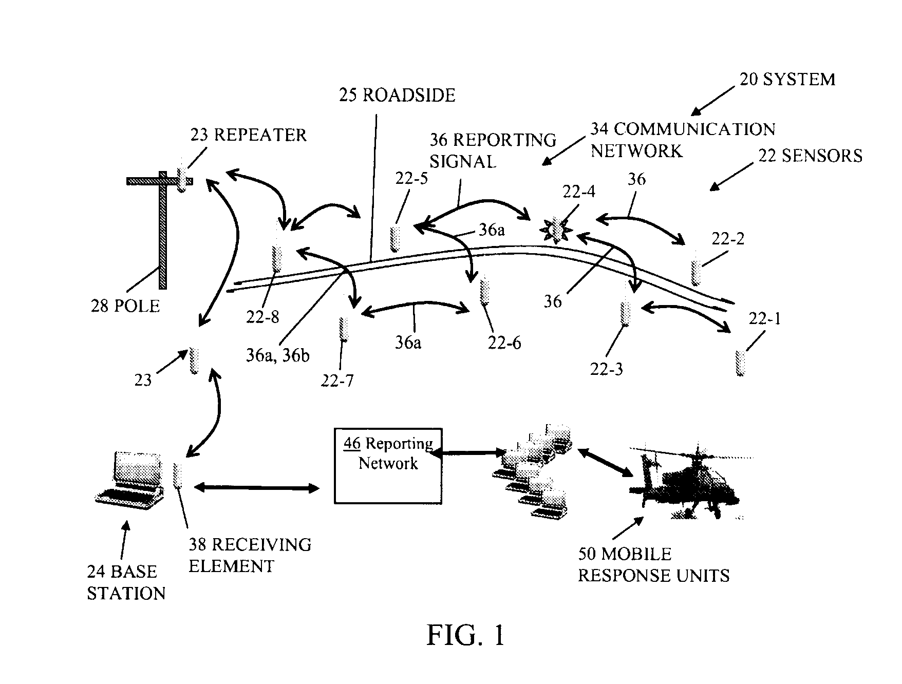
[0024]Embodiments of the invention are directed to techniques for detecting placement of an explosive device, such as an IED or landmine, within a particular geographic area. A detection system includes sensors and base station that detect and report on suspected IED emplacement activity within the area. When disposed within a geographic area, each sensor forms part of a wireless communications network which allows communication among neighboring sensors. As a sensor detects activity in its proximity, such as activity that indicates emplacement of an IED, the sensor transmits a reporting signal through the network to the base station. The neighboring sensors receive and transmit the reporting signal in a sequential manner toward the base station. Because the reporting signal takes multiple hops toward the base station, the sensors do not require large amounts of power to transmit the signal. Furthermore, the detection system allows detection of IED emplacement within the geographic ...


PUM


Abstract

An explosive device detection system includes sensors and base station that detect and report on suspected Improvised Explosive Devices (IED) or landmine emplacement activity within a geographic area. When disposed within a geographic area, each sensor forms part of a wireless communications network which allows communication among neighboring sensors. As a sensor detects activity in its proximity, such as activity that indicates emplacement of an IED, the sensor transmits a reporting signal through the network to the base station. The neighboring sensors receive and transmit the reporting signal in a sequential manner toward the base station. Because the reporting signal takes multiple hops toward the base station, the sensors do not require large amounts of power to transmit the signal. Furthermore, the detection system allows detection of IED emplacement within the geographic area as the activity occurs. As a result, the base station can direct mobile response units to take immediate responsive action to prevent detonation of the IED's.

Description

BACKGROUND[0001]Terrorist-type explosives, such as Improvised Explosive Devices or IED's, are a source of casualties both in military action and in peacetime. Certain IED's, such as roadside bombs, are formed of an explosive element, such as one or more 120 mm or 155 mm shells, and a radio controlled detonator. These IED's are placed along side roadways and typically hidden, buried, or camouflaged. In use, when a triggerman observes a target vehicle traveling toward an emplaced IED, the triggerman remotely detonates the IED using a remote control, thereby causing the IED to explode and cause damage to the target vehicle, injury to the vehicle's personnel, or both.[0002]In order to reduce the risk of an attack by way of such roadside IED's, military groups typically focus their efforts toward countering the effect of IED's after emplacement. For example, the military can send personnel and equipment to roadway locations in an attempt to visually detect the presence of IED's. Once det...

Claims


Application Information

Patent Timeline
IPC IPC(8): G08B1/08G08B13/14H04Q5/22H04W4/00H04L12/28
CPCG01V1/223
Inventor STEADMAN, ROBERT L.FITZGERALD, JAMES
Owner TEXTRON SYST
Why Eureka
Try Eureka