Positioning apparatus

a technology of positioning apparatus and moving member, which is applied in the direction of photomechanical apparatus, instruments, printers, etc., can solve the problems of increasing production costs, large size of entire stage apparatus, and large bending force of coarse-motion actuators, so as to reduce the amount of deformation of moving members and reduce bending force

Inactive Publication Date: 2011-10-04
CANON KK
View PDF29 Cites 24 Cited by
  • Summary
  • Abstract
  • Description
  • Claims
  • Application Information

AI Technical Summary

Benefits of technology

[0015]In another aspect of the present invention, a positioning apparatus includes a moving member, an actuator, and a controller. The moving member can move in at least a first direction. The actuator is provided along the first direction. The controller controls a current applied to the actuator in order to support the weight of the moving member. The controller controls the current so as to reduce the bending force exerted on the moving member as the moving member moves in the first direction.
[0018]This configuration can reduce the effect of the deformation caused by the change in the application point of force when the stage moves.

Problems solved by technology

Consequently, the coarse-motion actuator tends to be large, and the entire stage apparatus also tends to be large.
This tendency is undesirable because it causes an increase in the production cost and an increase in the area for installing the apparatus.
Such change in the application points of forces can cause undesirable deformation of the stage.
If the above-described deformation occurs, the positional relationship between the reflecting surface (mirror) and the exposure area on the wafer changes and therefore the exposure accuracy deteriorates.

Method used


Image

  • Positioning apparatus
  • Positioning apparatus
  • Positioning apparatus

Examples


embodiment 1

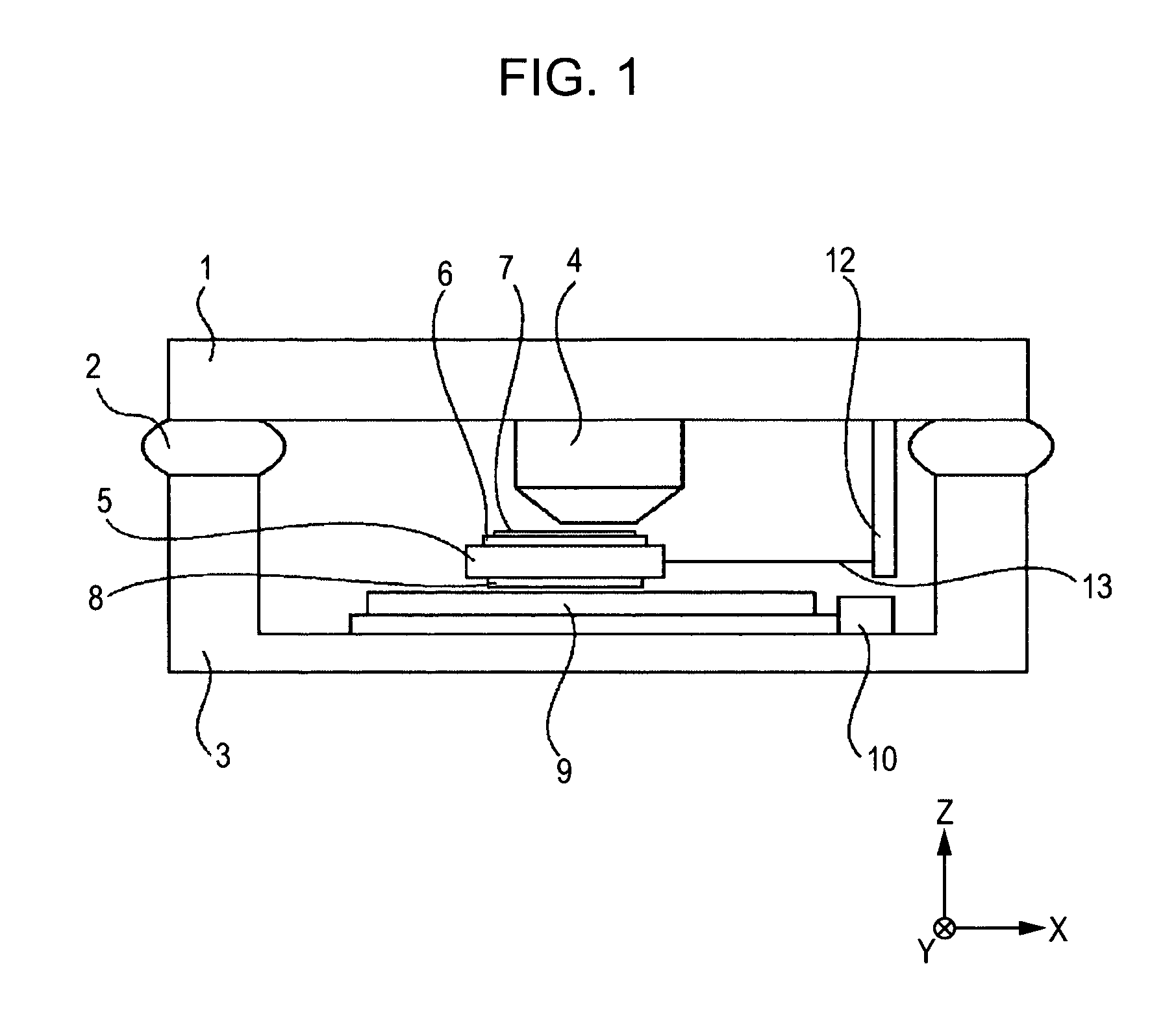
[0036]FIG. 1 is a schematic view of a semiconductor photolithography machine. A lens barrel supporting member 1 is mounted on a mount 3. The lens barrel supporting member 1 is insulated with a vibration absorber 2 so as to be insulated against vibrations from the floor. A projection optical system 4 is supported by the lens barrel supporting member 1. A reticle stage (not shown) is provided above the projection optical system 4. A wafer stage 5 is provided below the projection optical system 4.

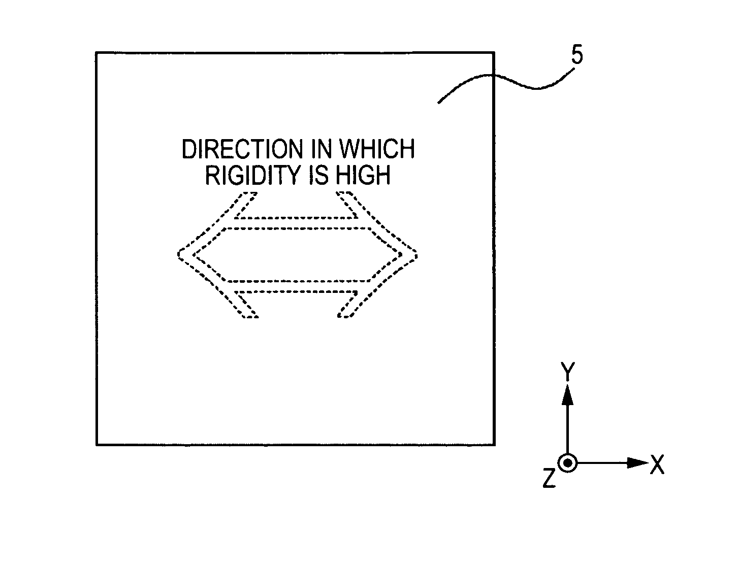
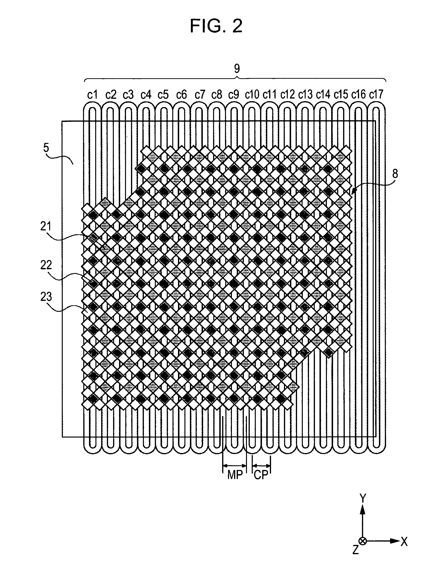
[0037]A wafer 7 is mounted on the wafer stage (mover) 5 with a wafer chuck 6. The wafer stage 5 can be moved with a so-called surface motor. The surface motor includes a magnet unit 8 and a coil unit (stator) 9. The magnet unit 8 is provided on the underside of the wafer stage 5. The coil unit 9 is provided on the mount 3. The surface motor will hereinafter be described in detail.

[0038]When the wafer stage 5 is driven, a reaction force is exerted on the coil unit 9. In order to prevent the rea...


PUM


Abstract

A positioning apparatus includes a moving member, an actuator, and a controller. The moving member can move in at least a first direction. The actuator is provided along the first direction. The controller controls a current applied to the actuator in order to support the weight of the moving member. The bending rigidity of the moving member in the first direction is greater than the bending rigidity of the moving member in a second direction perpendicular to the first direction.

Description

BACKGROUND OF THE INVENTION[0001]1. Field of the Invention[0002]The present invention relates to a positioning apparatus, and more specifically, it relates to a positioning apparatus used for positioning a substrate in a photolithography machine.[0003]2. Description of the Related Art[0004]A semiconductor photolithography machine makes exposure light incident on an original pattern drawn on a reticle. The light transmitted or reflected by the reticle is reduced with an exposure optical system, and the reduced pattern is projected onto a semiconductor substrate (wafer). In this way, a semiconductor photolithography machine performs exposure operation. The reticle having the pattern to be transferred is mounted on a reticle stage and positioned at a predetermined position. The reticle is irradiated from above with exposure light by an illumination system. The exposure light then enters a reduced projection optical system. This optical system forms an image at a predetermined position....

Claims


Application Information

Patent Timeline
Patent Type & Authority Patents(United States)
IPC IPC(8): G03B27/58H02K41/02
CPCH02K41/03G03F7/70783G03F7/70775G03F7/70758H02K2201/18
Inventor ASANO, TOSIYASHIBATA, YUGOKIMURA, ATSUSHI
Owner CANON KK
Why Eureka
Try Eureka