Transmitting digital signal

a digital signal and signal technology, applied in the field of digital signal transmission, can solve the problems of interference to telecommunications, interference that may change, and the solution is, however, very difficult to implement, and achieve the advantages of the bit error rate, full diversity, and the coding rate of the code matrix

Inactive Publication Date: 2011-10-04
UNWIRED BROADBAND INC
View PDF39 Cites 2 Cited by
  • Summary
  • Abstract
  • Description
  • Claims
  • Application Information

AI Technical Summary

Benefits of technology

[0027]The invention provides significant advantages. The coding rate of the code matrix can be made higher than the coding rate allowed by orthogonality, and by weighting one or more symbols by a complex weighting coefficient, the invention enables the presentation of a code matrix that achieves full diversity. The solution of the invention provides significant advantages in the level of the bit error rate (BER) in comparison with the prior art solution, especially at high signal-to-noise ratios (SNR).

Problems solved by technology

As is well known, the transmission path used for the transmission of signals in telecommunications connections causes interference to telecommunications.
Other simultaneous connections can also cause interference that may change with time and location.
In practice, such a solution is, however, very difficult to implement, because firstly, the transmitter should know the quality of the channel, and transmitting this information to the transmitter in real time is difficult.
Secondly, transmission power restrictions set on transmitters and the dynamic range of transmitters set their own limitations.
In addition, power control in itself may lead to ineffective transmission by increasing power to a high level in fading dips.
However, this has the drawback that it causes delays in the transmission especially when the channel is a slow-fading one.
This is, however, an ineffective method when the coherence bandwidth of the channel is wide.
Known non-orthogonal block codes do, however, contain a significant drawback.
Said block codes do not have full diversity, i.e. the number of independently decoded channels is smaller than the number of antennas, whereby transmission capacity provided by the antennas is lost.

Method used


Image

  • Transmitting digital signal
  • Transmitting digital signal
  • Transmitting digital signal

Examples


Embodiment Construction

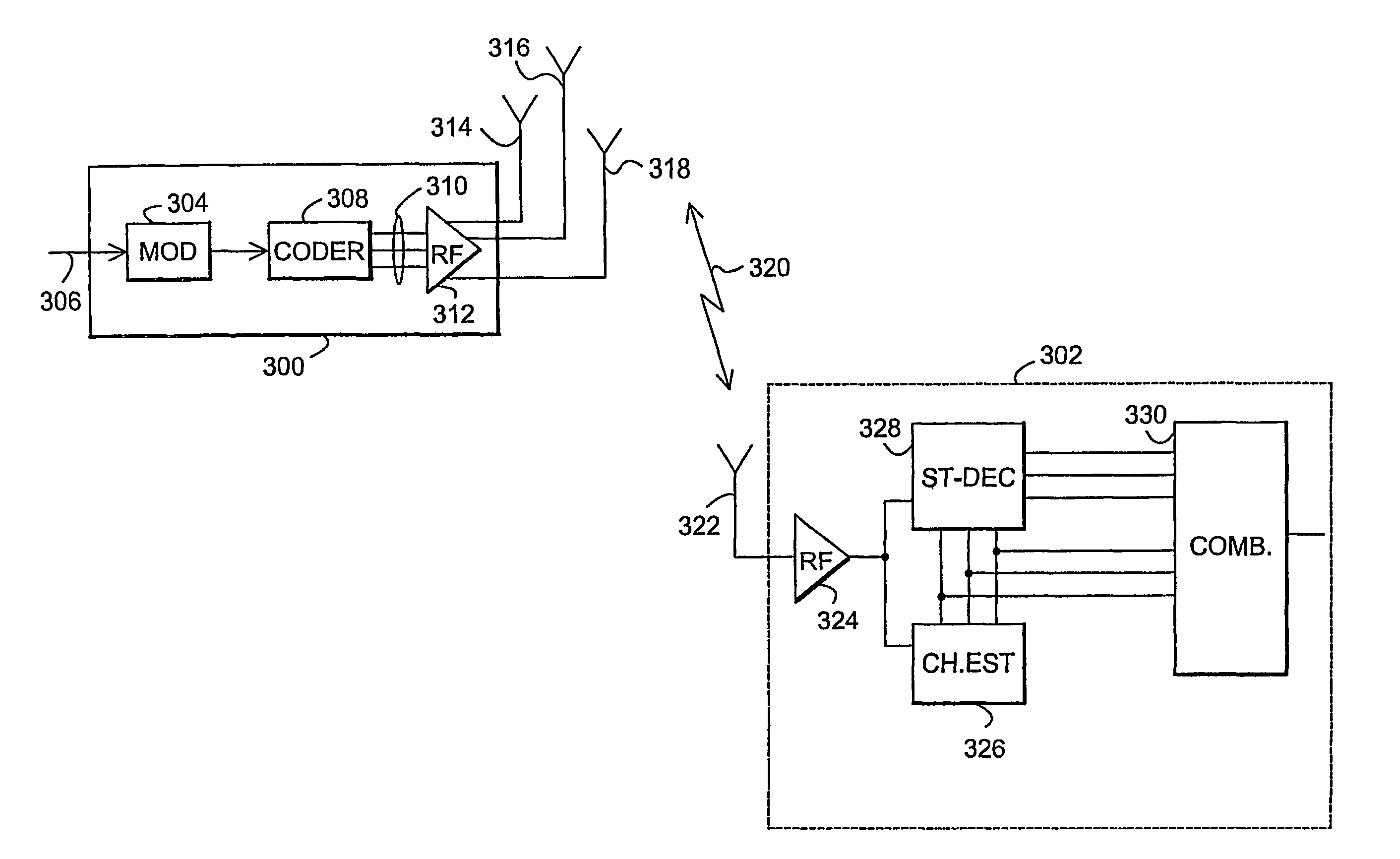
[0035]The invention can be used in radio systems, in which it is possible to transmit at least a part of a signal by using two or more transmission antennas or two or more lobes provided by two or more transmission antennas. The transmission channel can be established using a time-division, frequency-division, or code-division symbol multiplexing or multiple access method. Systems using combinations of different multiple access methods are also systems of the invention. The examples describe the use of the invention in a UMTS (Universal Mobile Telephony System) system employing a wide-band code-division multiple-access method implemented by a direct sequence technique, without limiting the invention to it, however.

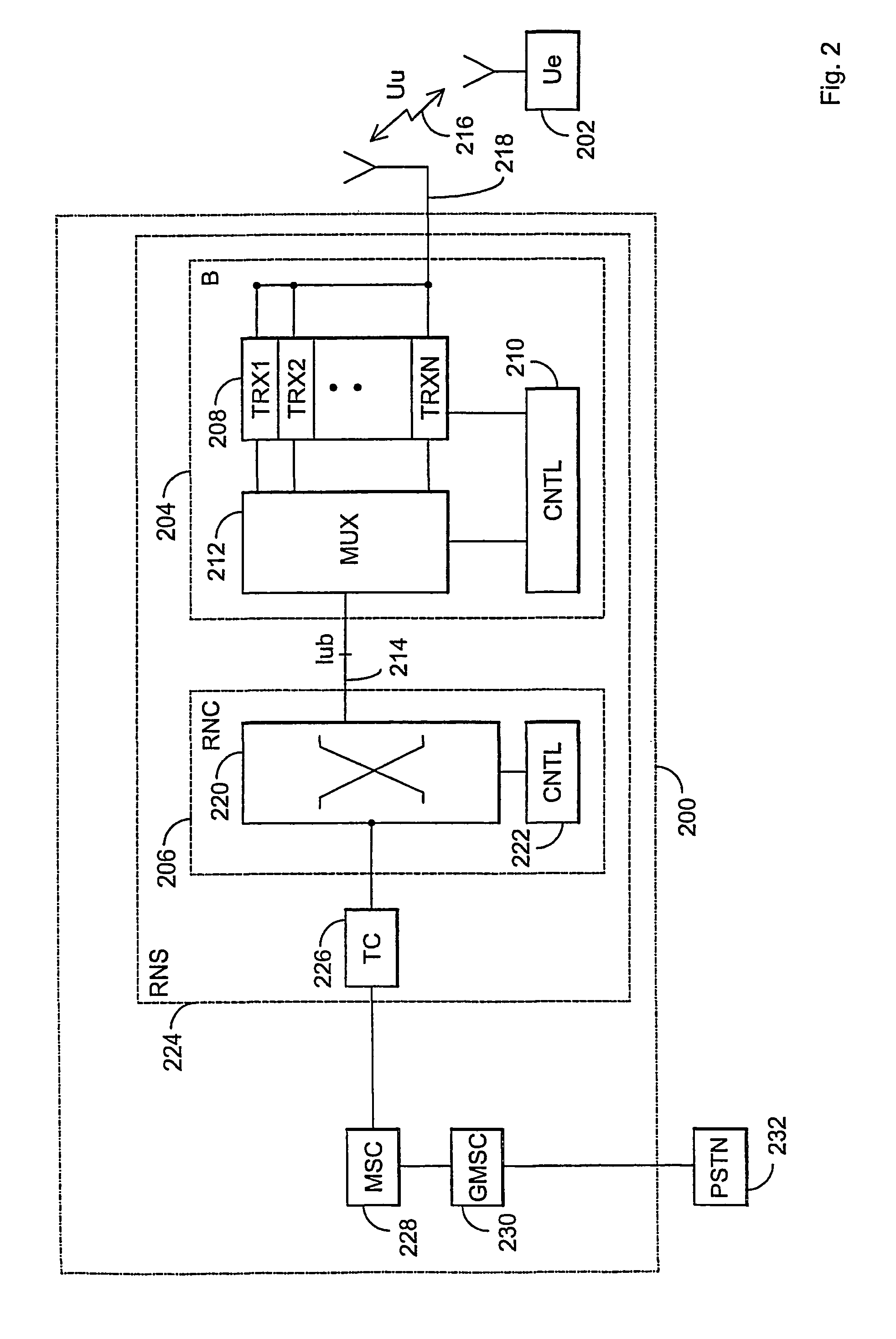
[0036]The structure of a mobile system is described by way of example with reference to FIG. 1. The main parts of the mobile system are a core network CN, a UMTS terrestrial radio access network UTRAN and user equipment UE. The interface between CN and UTRAN is called Iu a...


PUM


Abstract

An arrangement for coding digital symbols and transmitting them through at least two antennas. A coder reads at least two symbols belonging to the same transmission block and forms channel symbols of the symbols of the transmission block by means of a block code. The coder multiplies at least one symbol belonging to the transmission block by a first nonzero weighting coefficient and at least one symbol belonging to the transmission block by a second nonzero weighting coefficient, and the division ratio of the first and second weighting coefficients differs from values ±1, ±j and ±1 / sqrt(2). The thus formed channel symbols are transmitted to the radio path through the antennas.

Description

FIELD OF THE INVENTION[0001]The field of application of the invention is the transmission of a digital signal, the invention relates especially to the block coding of a signal for transmission through more than one antenna.BACKGROUND OF THE INVENTION[0002]As is well known, the transmission path used for the transmission of signals in telecommunications connections causes interference to telecommunications. This occurs regardless of the physical form of the transmission path, whether it is a radio link, optical fibre or copper cable. Especially in radio communications, there are often situations, in which the quality of the transmission path varies from one connection to another and even during a connection. Fading of the radio path is one typical phenomenon that causes changes in the transmission channel. Other simultaneous connections can also cause interference that may change with time and location. In a typical radio communications environment, signals between a transmitter and ...

Claims


Application Information

Patent Timeline
Patent Type & Authority Patents(United States)
IPC IPC(8): H04L27/00H04L1/06
CPCH04L1/0618
Inventor TIRKKONEN, OLAV
Owner UNWIRED BROADBAND INC
Why Eureka
Try Eureka