Multiple piece turbine engine airfoil with a structural spar

a turbine engine and airfoil technology, applied in the field of airfoils, can solve the problems of high heat load of typical materials capable of handling the high heat load of exhaust gases, still hot spots in airfoils, and present manufacturing challenges, and achieve the effect of less melting point and less cos

Inactive Publication Date: 2011-10-11
SIEMENS ENERGY INC
View PDF30 Cites 26 Cited by
  • Summary
  • Abstract
  • Description
  • Claims
  • Application Information

AI Technical Summary

Benefits of technology

[0005]This invention relates to a multiple piece turbine airfoil formed, from a plurality of components. Forming the turbine airfoil from a plurality of components in a modular fashion enables at least some of the components to be formed from materials that are specifically suited for each component. In particular, the components may be formed from materials capable of being exposed to the localized heat loads without requiring that the entire turbine airfoil be formed from the materials capable of handling the high temperature exhaust gases. Thus, components not exposed to the high temperature exhaust gases may be formed from other materials having lower melting points, which are typically less expensive.
[0011]An advantage of this invention is that the turbine airfoil support system of the instant invention is formed from a plurality of components in a modular manner that enables the components to be formed from different materials such that less expensive, low melting point materials may be used with internal components not subjected to the hot gas flow path.
[0012]Another advantage of this invention is that the turbine airfoil support system of the instant invention is formed from a plurality of components in a modular manner that enables parts to be more easily manufactured than conventional monolithic airfoils.
[0013]Yet another advantage of this invention is that the turbine airfoil support system of the instant invention enables the outer wall of the airfoil component to be loaded with a compressive force at the perimeter of the airfoil that enhances the ability of the airfoil to absorb tensile forces during turbine engine operation without airfoil failure. Specifically, application of the compressive forces at the perimeter of the airfoil concentrates compressive forces at the perimeter of the airfoil and reduces the likelihood of failure at the fillets at the transition between the airfoil and the platforms.

Problems solved by technology

In addition, turbine airfoils often contain internal cooling systems for prolonging the life of the airfoils and reducing the likelihood of failure as a result of excessive temperatures.
While much attention has been paid to cooling technologies, hot spots still occur in the airfoils.
Typical materials capable of handling the high heat loads of the exhaust gases are often expensive and present manufacturing challenges.

Method used


Image

  • Multiple piece turbine engine airfoil with a structural spar
  • Multiple piece turbine engine airfoil with a structural spar
  • Multiple piece turbine engine airfoil with a structural spar

Examples


Embodiment Construction

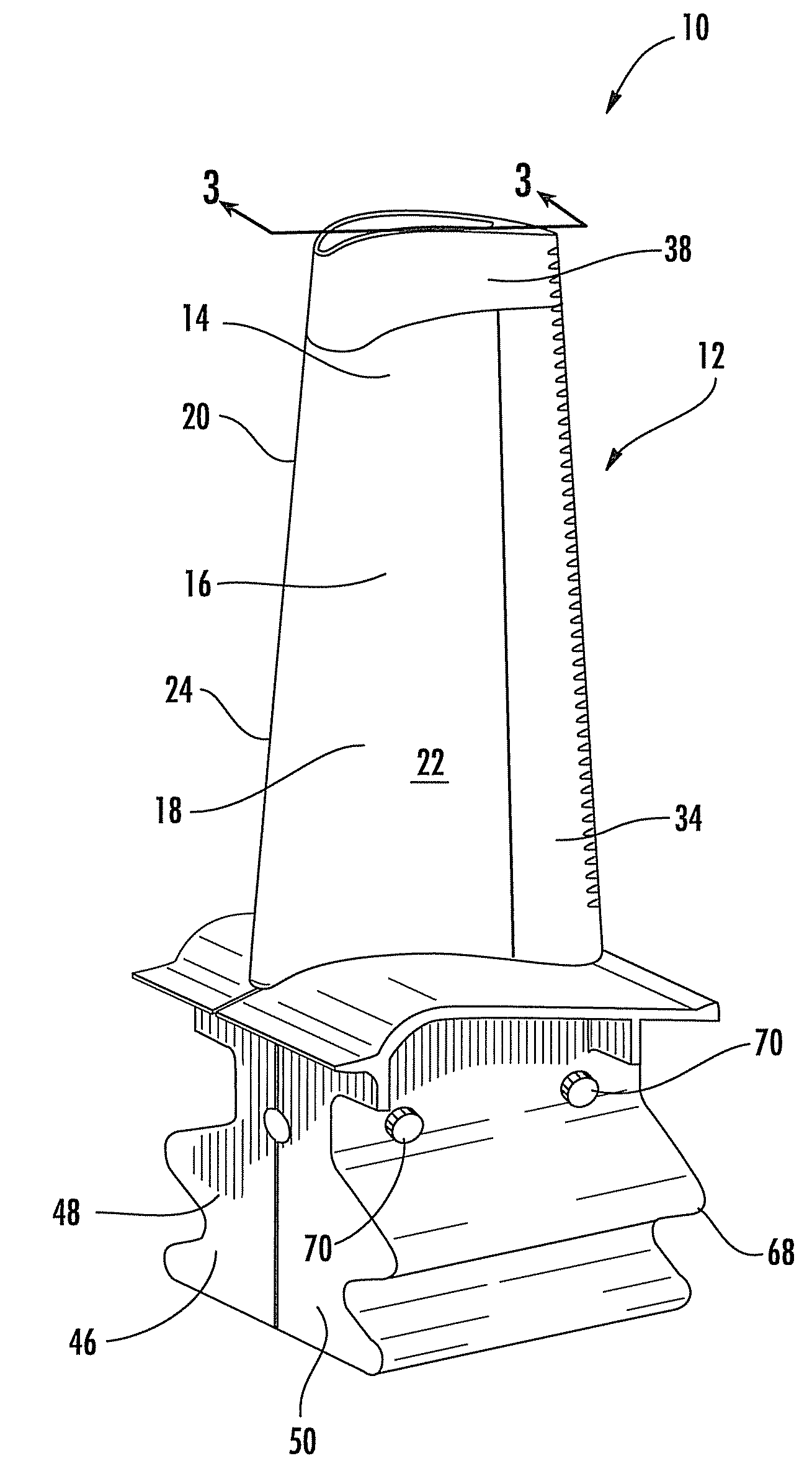
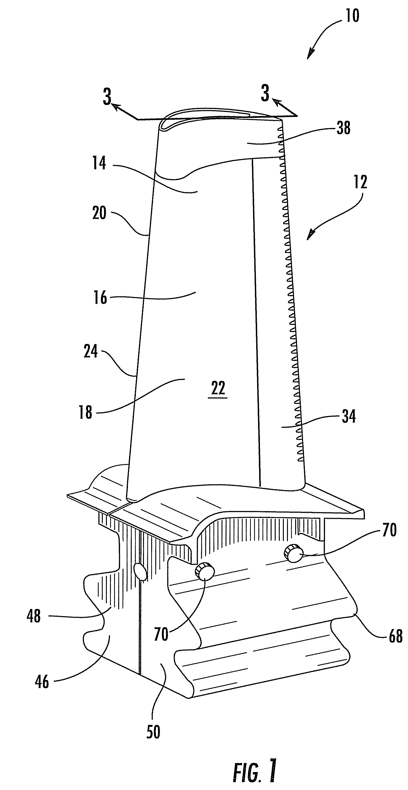
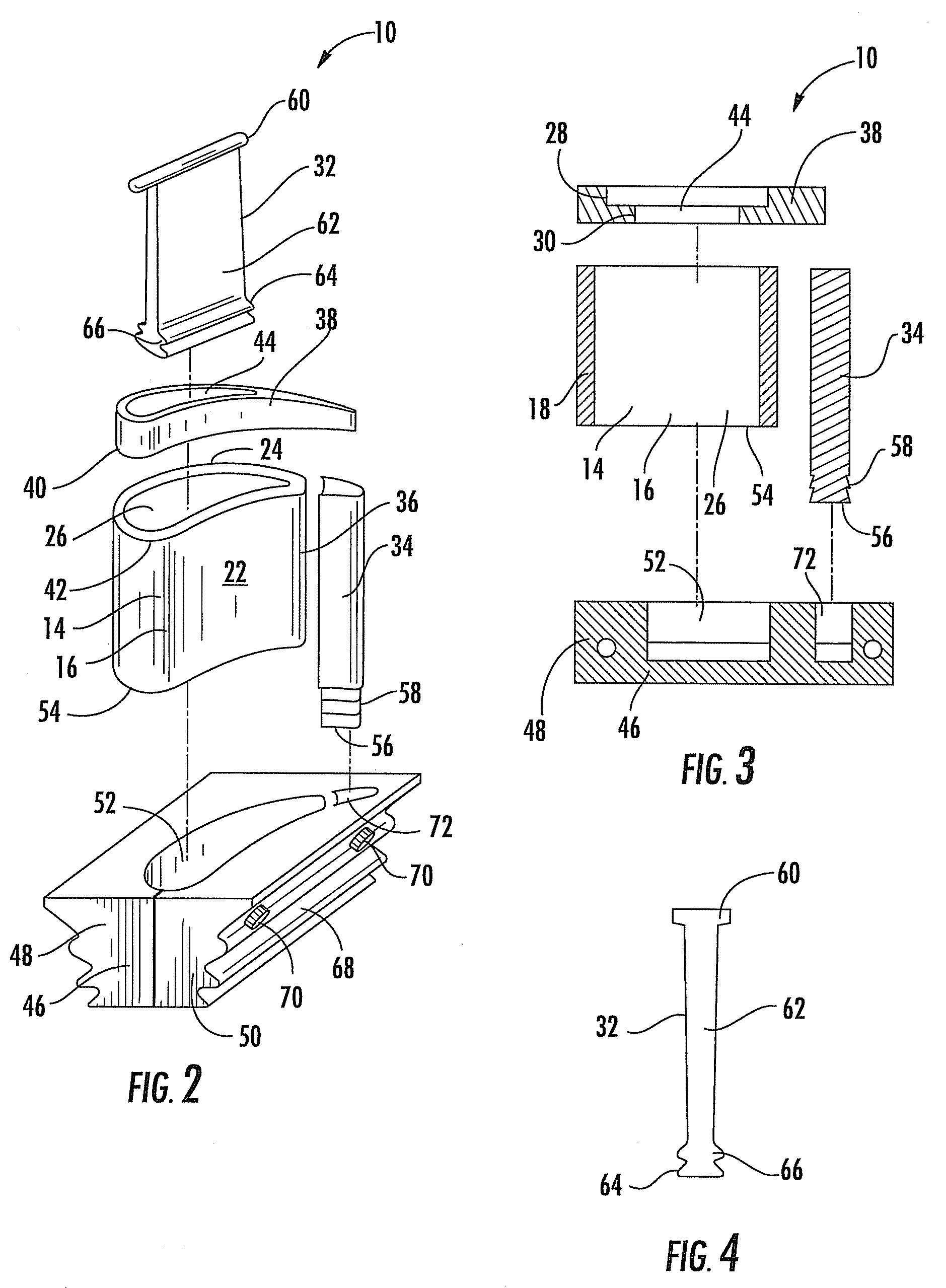
[0023]As shown in FIGS. 1-7, this invention is directed to a multiple piece turbine airfoil 10 formed from a plurality of components 12. Forming the turbine airfoil 10 from a plurality of components 12 in a modular fashion enables at least some of the components to be formed from materials that are specifically suited for each component. In particular, the components 12 may be formed from materials capable of being exposed to the localized heat loads without requiring that the entire turbine airfoil 10 be formed from the materials capable of handling the high temperature exhaust gases. Thus, components 12 not exposed to the high temperature exhaust gases may be formed from other materials having lower melting points, which are typically less expensive.

[0024]The multiple piece turbine airfoil 10 may be formed from one or more components 14 forming a generally elongated airfoil 16 with an outer wall 18 having a leading edge 20, a pressure side 22, and a suction side 24. The airfoil 16...


PUM


Abstract

A multiple piece turbine airfoil having an outer shell with an airfoil tip that is attached to a root with an internal structural spar is disclosed. The root may be formed from first and second sections that include an internal cavity configured to receive and secure the one or more components forming the generally elongated airfoil. The internal structural spar may be attached to an airfoil tip and place the generally elongated airfoil in compression. The configuration enables each component to be formed from different materials to reduce the cost of the materials and to optimize the choice of material for each component.

Description

STATEMENT REGARDING FEDERALLY SPONSORED RESEARCH[0001]Development of this invention was supported in part by the United States Department of Energy, Contract No. DE-FC26-05NT42646. Accordingly, the United States Government may have certain rights in this invention.FIELD OF THE INVENTION[0002]This invention is directed generally to airfoils usable in turbine engines, and more particularly to a multiple piece airfoil.BACKGROUND[0003]Typically, gas turbine engines include a compressor for compressing air, a combustor for mixing the compressed air with fuel and igniting the mixture, and a turbine blade assembly for producing power. Combustors often operate at high temperatures that may exceed 2,500 degrees Fahrenheit. Typical turbine combustor configurations expose turbine vane and blade assemblies, to these high temperatures. As a result, turbine airfoils, such as turbine vanes and blades must be made of materials capable of withstanding such high temperatures. In addition, turbine air...

Claims


Application Information

Patent Timeline
Patent Type & Authority Patents(United States)
IPC IPC(8): F01D5/30
CPCF01D5/147F01D5/18F01D5/28F05D2230/51F05D2230/50
Inventor VANCE, STEVEN J.
Owner SIEMENS ENERGY INC
Why Eureka
Try Eureka