Systems and methods to stir an electromagnetic (EM) field

a technology of electromagnetic field and electromagnetic field, applied in waveguide type devices, base element modifications, instruments, etc., can solve the problems of step motors that cannot be scaled, illustrations are merely representational, and cannot be used to scal

Inactive Publication Date: 2011-10-11
THE BOEING CO
View PDF13 Cites 8 Cited by
  • Summary
  • Abstract
  • Description
  • Claims
  • Application Information

AI Technical Summary

Problems solved by technology

Such step motors can be expensive.
Additionally, the illustrations are merely representational and may not be drawn to scale.

Method used


Image

  • Systems and methods to stir an electromagnetic (EM) field
  • Systems and methods to stir an electromagnetic (EM) field
  • Systems and methods to stir an electromagnetic (EM) field

Examples


Embodiment Construction

[0014]The features, functions, and advantages that are discussed can be achieved independently in various embodiments disclosed herein or may be combined in yet other embodiments further details of which can be shown with reference to the following description and drawings.

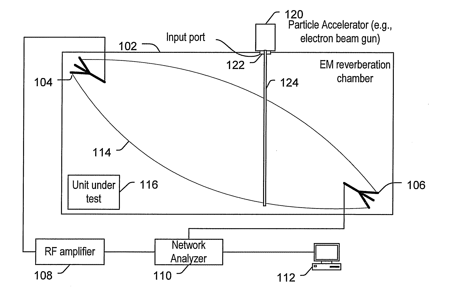
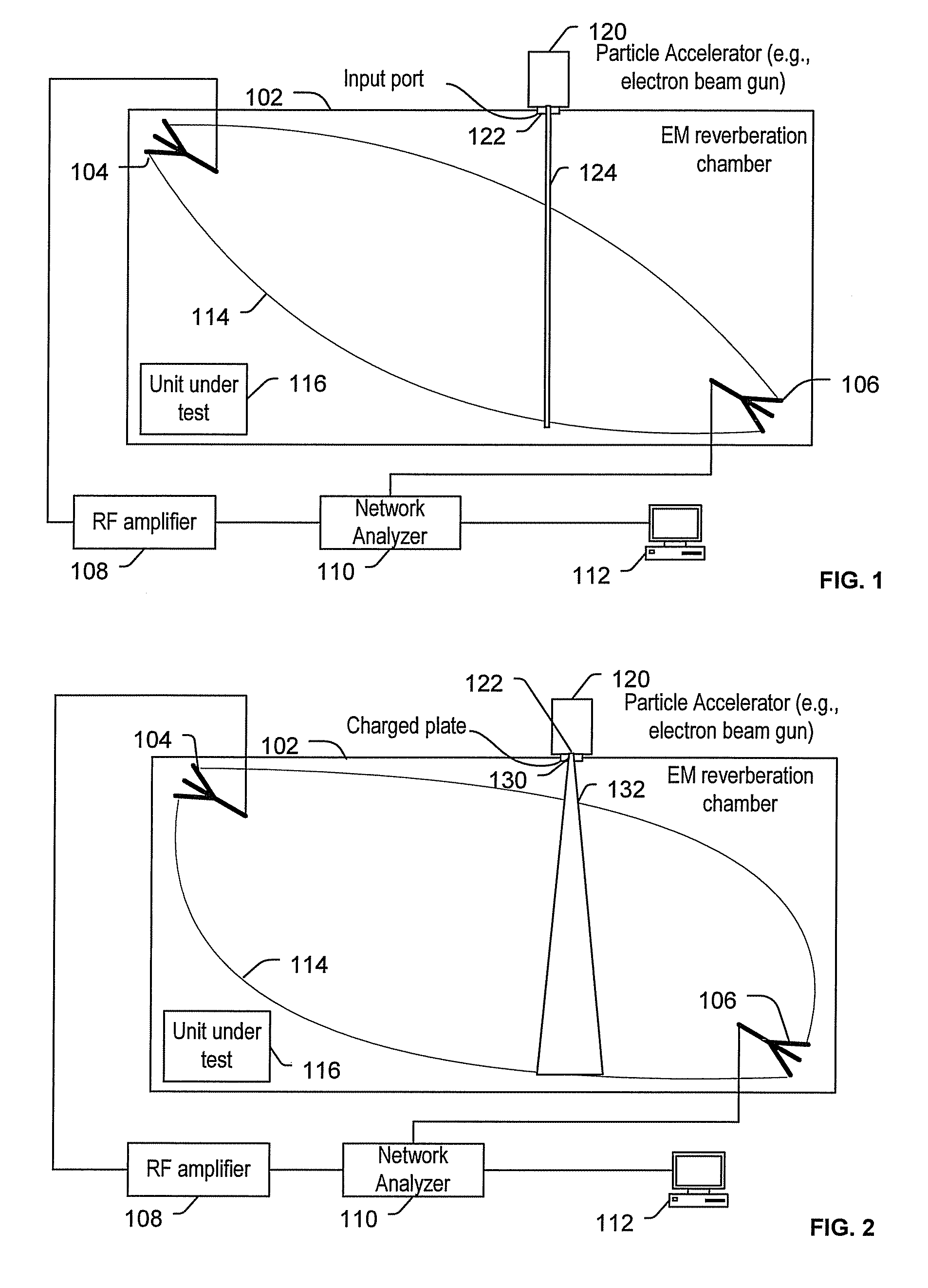
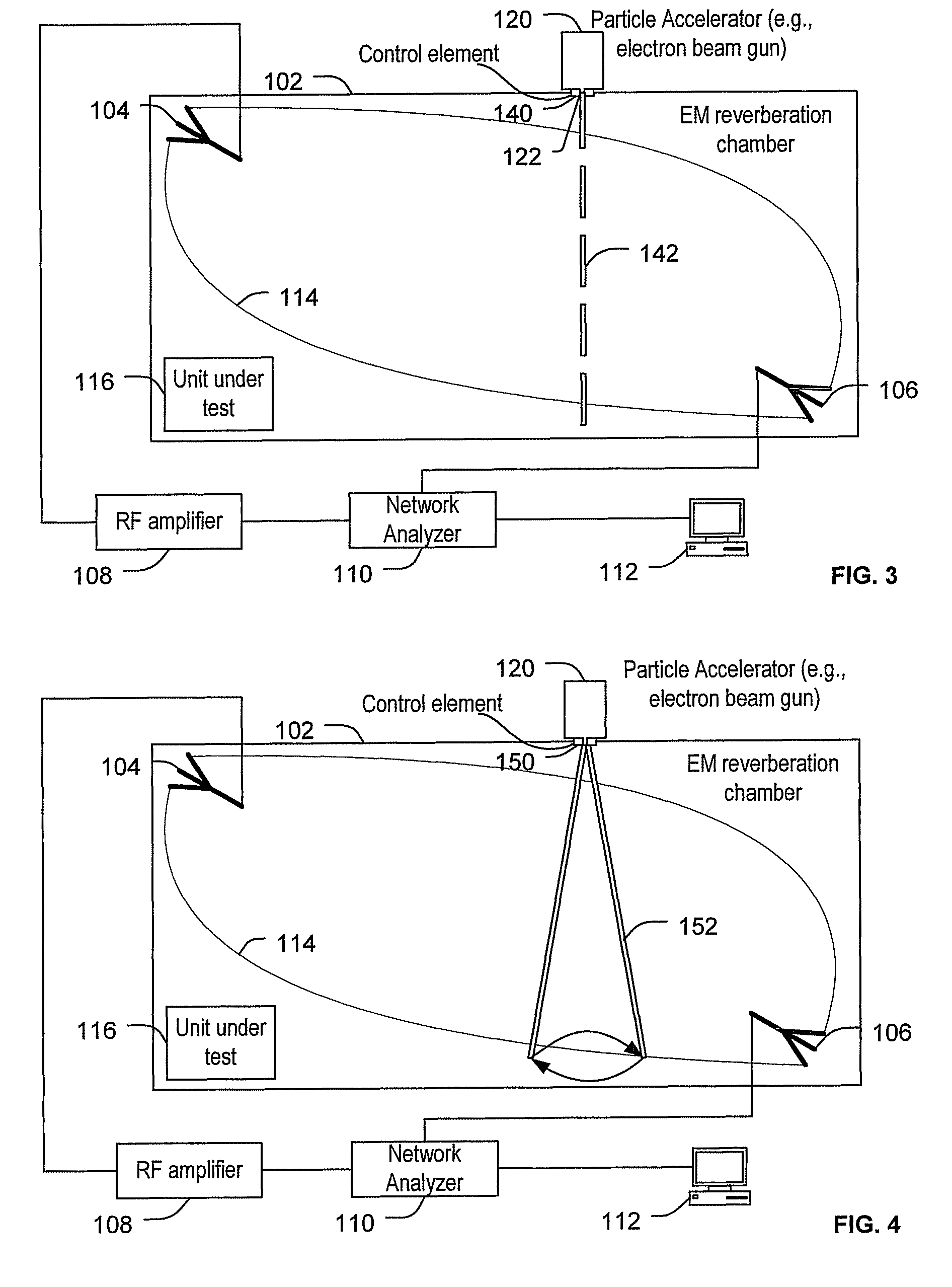
[0015]Particular systems and methods described below can be used to stir electromagnetic (EM) fields in EM reverberation chambers. In particular, the systems and methods enable stirring of the EM fields without the use of mechanical stirring devices, such as moveable metal paddles. Avoiding the use of mechanical stirring devices may reduce the cost of the EM reverberation chambers. Additionally, since mechanical stirring devices may be large and may be placed within the EM reverberation chamber, eliminating the mechanical stirring devices may allow more of the EM reverberation chamber to be used or may allow smaller EM reverberation chambers to be used.

[0016]Further, particular moveable metal paddles may be design...


PUM


Abstract

Systems and methods to stir an electromagnetic (EM) field of an EM reverberation chamber are disclosed. A particular system includes an EM reverberation chamber. The system also includes a transmit antenna and a receive antenna operable to generate an EM field within the EM reverberation chamber. The system further includes a variable charged particle source to stir the EM field by varying introduction of charged particles into the EM field.

Description

FIELD OF THE DISCLOSURE[0001]The present disclosure is generally related to stirring an electromagnetic (EM) field.BACKGROUND[0002]Electromagnetic (EM) reverberation chambers are used to perform various tests on devices. For certain tests, an EM reverberation chamber subjects a device under test to an EM field. The EM reverberation chamber may include a stirring device to stir the EM field. For example, the EM reverberation chamber may include a movable metal paddle that is moved to stir the EM field.SUMMARY[0003]Systems and methods to stir an electromagnetic (EM) field of an EM reverberation chamber are disclosed. In a particular embodiment, a system includes an EM reverberation chamber. The system also includes a transmit antenna and a receive antenna operable to generate an EM field within the EM reverberation chamber. The system further includes a variable charged particle source to stir the EM field by varying the introduction of charged particles into the EM field.[0004]In ano...

Claims


Application Information

Patent Timeline
Patent Type & Authority Patents(United States)
IPC IPC(8): G01R1/20G01R31/308
CPCG01R29/0821
Inventor JACKSON, DANIEL P.LEWIS, DENNIS M.KOEHN, JASON A.RUSSELL, DENNIS A.
Owner THE BOEING CO
Why Eureka
Try Eureka