
Laminated tube for the transport of charged particles contained in a gaseous medium

a gaseous medium and charged particle technology, applied in particle separator tube details, electron/ion optical arrangements, separation processes, etc., can solve the problems of limiting the acceptance and transmission efficiency, low sampling efficiency through conductance or transmission apertures and capillaries or tubes, and dispersive sources of ions at or near atmospheric pressure. , to achieve the effect of reducing the gas load

Inactive Publication Date: 2005-09-13
CHEM SPACE ASSOIATES
View PDF15 Cites 140 Cited by
  • Summary
  • Abstract
  • Description
  • Claims
  • Application Information

AI Technical Summary

Benefits of technology

[0038](c) to provide a laminated tube the restricts the flow of gas into the lower pressure regions, thereby reducing the gas-load on the device and any vacuum pumping associated with these re

Problems solved by technology

Dispersive sources of ions at or near atmospheric pressure, such as, atmospheric pressure discharge ionization, chemical ionization, photoionization, or matrix assisted laser desorption ionization, and electrospray ionization, generally have low sampling efficiency through conductance or transmission apertures and capillaries or tubes.
Unfortunately, this mainstream commercial technology2 transmits only a fraction of a percent of typical atmospheric pressure generated ions into the vacuum.
This dependence of surface charging limits the acceptance and transmission efficiencies of Fenn et al.
In addition, since a large amount of energy is stored within the capillary, contamination can lead to electrical discharges and damage to the capillary, sometimes catastrophic.
The efficiencies of these devices are low as well.
Drops undergoing coulomb explosions inside of a restricted volume of the lumen of the capillary will tend to cause dispersion losses to the walls were the charges are quickly neutralized and: not resulting in the surface charging up.
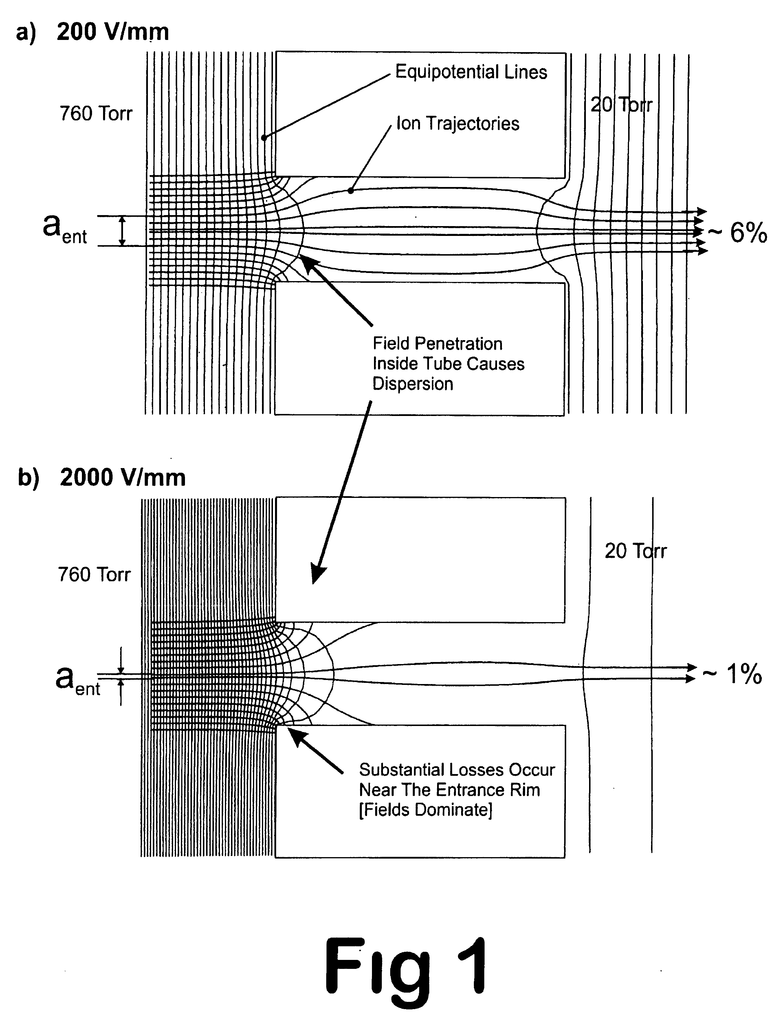
's dielectric capillary, this technique suffers the same limitation from losses at the inlet due to the dispersive electric fields (FIG.
However, they failed to identify field dispersion at the inlet as the first step in the loss of ions.
Although it is difficult to distinguish this art from Fenn et al.
Irregardless, Franzen's approach will suffer from the same limitations as Fenn's, that is loss of ions in the dispersive electric fields at the inlets of capillaries and apertures.
This approach addresses the problem of charge accumulation on the inner-surfaces, but it does not remove the significant losses of ions at the inlet due to dispersion (FIG.
With this device, a higher ion population can be presented to the conductance opening at the expense of higher field ratios across the aperture or along the capillary but at the expense of higher dispersion losses inside the aperture or tube.
This device frankly will not work.
Most of the inertial energy acquired by the ions in the source region is lost to collisions with neutral gas molecules at atmospheric pressure; consequently the only energy driving the ions in the direction of the capillary inlet or aperture will be the gas flow which under normal gas flows would be insufficient to push the ions up the field gradient imposed by the funnel optics.
(U.S. Pat. No. 6,359,275 B1) to eliminate surface charging, all three devices do not address issues related to inlet losses due to dispersive electric fields at the inlets of capillaries and apertures, as presented in FIG.
In addition, all these devices still utilize significantly large dielectric inner-surfaces with the associated problems with surface charging, contamination, and discharge.

Method used


Image

  • Laminated tube for the transport of charged particles contained in a gaseous medium
  • Laminated tube for the transport of charged particles contained in a gaseous medium
  • Laminated tube for the transport of charged particles contained in a gaseous medium

Examples


Embodiment Construction

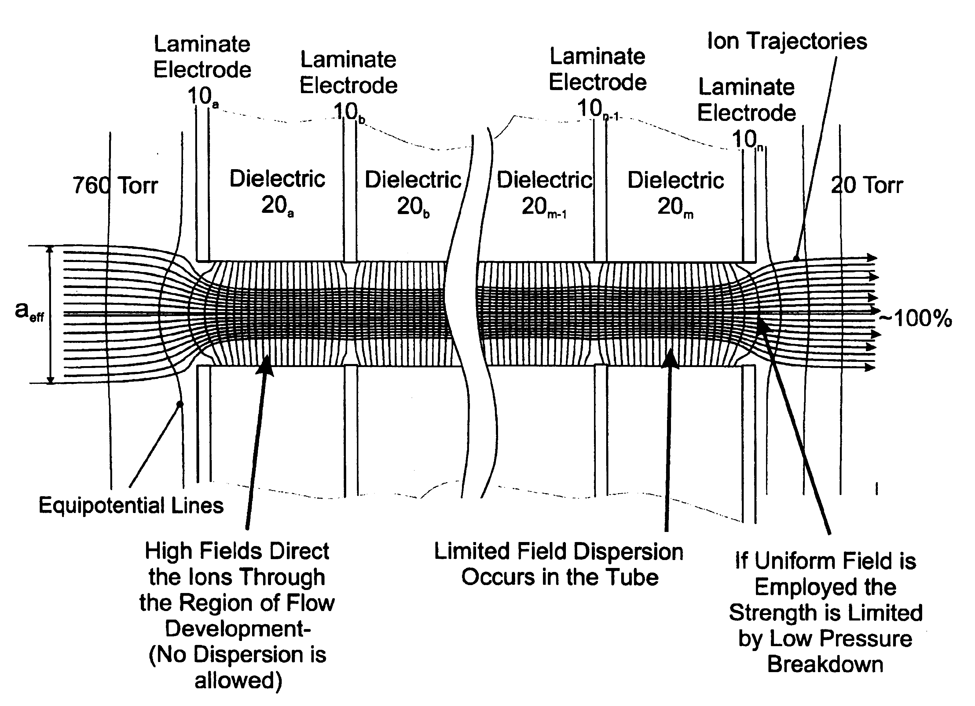
[0103]A preferred embodiment of the laminated-tube or just tube of the present invention is illustrated in FIG. 5A, FIG. 7, and FIG. 10. The tube is made-up of a series of thin concentric planar metal laminates or layers 10, designated 10a, 10b, 10c, . . . 10n−2, 10n−1, 10n, separated from each other by a thin base layers 20, designated 20a through 20m, of uniform cross section and thickness consisting of non-conducting insulating material, the aggregate of metal laminatelbase pairs forming a lumen, defined by a laminatelbase inner surface or lumen 30. The tube thus has an entry 40 and an exit aperture 50 for introducing gases and gas-phase ions or charged particles from a tube entrance region 2 into a tube exit region 3 where they are transported toward an ion-collection region 70. Ions from a source region 1 and a small portion of the gases are transferred to an ion-collection region 70, as shown by the general direction of ion flow 18.

[0104]The collection region 70 in this embodi...


PUM


Abstract

An improved tube for accepting gas-phase ions and particles contained in a gas by allowing substantially all the gas-phase ions and gas from an ion source at or greater than atmospheric pressure to flow into the tube and be transferred to a lower pressure region. Transport and motion of the ions through the tube is determined by a combination of viscous forces exerted on the ions by the flowing gas molecules and electrostatic forces causing the motion of the ions through the tube and away from the walls of the tube. More specifically, the tube is made up of stratified elements, wherein DC potentials are applied to the elements so that the DC voltage on any element determines the electric potential experience by the ions as they pass through the tube. A precise electrical gradient is maintained along the length of the stratified tube to insure the transport of the ions. Embodiments of this invention are methods and devices for improving the sensitivity of mass spectrometry or ion mobility spectrometers when coupled to atmospheric and above atmospheric pressure ionization sources. An alternate embodiment of this invention applies an AC voltage to one or more of the conducting elements in the laminate.

Description

CROSS-REFERENCE TO RELATED APPLICATION[0001]This application claims the benefit of Provisional Patent Application Ser. No. 60 / 419,699, filed 2002, Oct. 18. This application is related to Provisional Patent Application Ser. No. 60 / 210,877, filed Jun. 9, 2000 now patent application Ser. No. 09 / 877,167, Filed Jun. 8, 2001; Provisional Patent Application Ser. No. 60 / 384,864, filed Jun. 1, 2002 now patent Application Ser. No. 10 / 449,344, Filed May 30, 2003; Provisional Patent Application Ser. No. 60 / 384,869, filed Jun. 1, 2002 now patent Application Ser. No. 10 / 449,147, Filed May 31, 2003; Provisional Patent Application Ser. No. 60 / 410,653, filed Sep. 13, 2002 now patent application Ser. No. 10 / 661,842, filed Sep. 12, 2003; and Provisional Patent application Ser. No. 60 / 476,582, filed Jun. 7, 2003.FEDERALLY SPONSORED RESEARCH[0002]The invention described herein was made with United States Government support under Grant Number: 1 R43 RR143396-1 from the Department of Health and Human Serv...

Claims


Application Information

Patent Timeline
IPC IPC(8): H01J49/02H01J49/06
CPCH01J49/0404
Inventor WILLOUGHBY, ROSS CLARKSHEEHAN, EDWARD WILLIAM
Owner CHEM SPACE ASSOIATES
Learn More