
Illumination system and liquid crystal display

a liquid crystal display and illumination system technology, applied in the direction of instruments, lighting and heating apparatus, spectral modifiers, etc., can solve the problem of loss of color balance of illumination light, and achieve the effect of improving the quality of the displayed imag

Inactive Publication Date: 2011-10-11
SONY CORP
View PDF20 Cites 31 Cited by
  • Summary
  • Abstract
  • Description
  • Claims
  • Application Information

AI Technical Summary

Benefits of technology

The system effectively varies light emission intensity while preserving color balance, enhancing the quality of displayed images by individually controlling the lighting periods and intensities of each light source.

Problems solved by technology

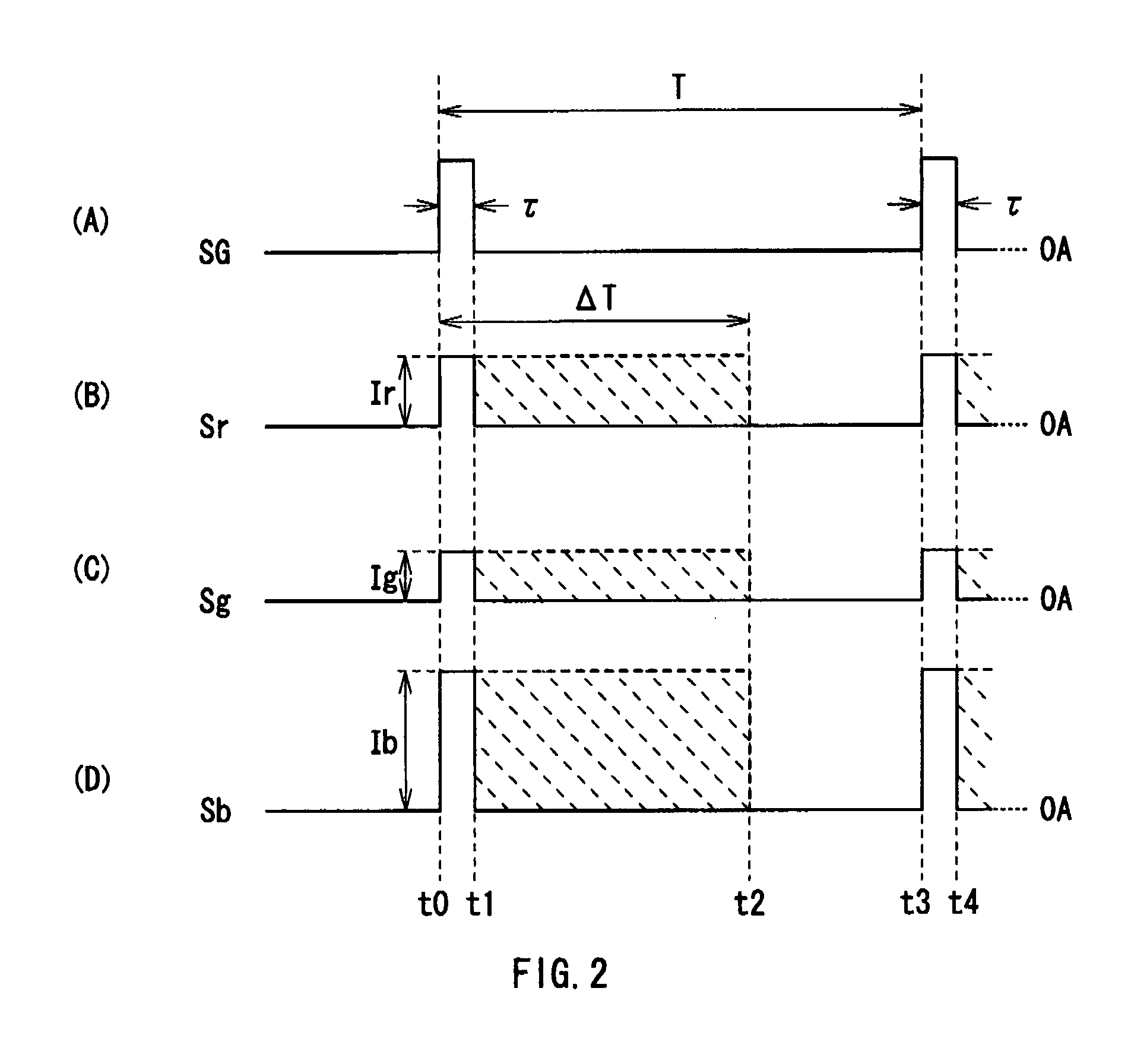
However, in such PWM control, a light emission intensity is controlled only by the length (width) of the lighting period of each color LED, so in the case where the light emission intensity is adjusted by changing the width of the lighting period, the color balance of illumination light is lost (a chromaticity point is moved).

Method used


Image

  • Illumination system and liquid crystal display
  • Illumination system and liquid crystal display
  • Illumination system and liquid crystal display

Examples


first embodiment

[0040]

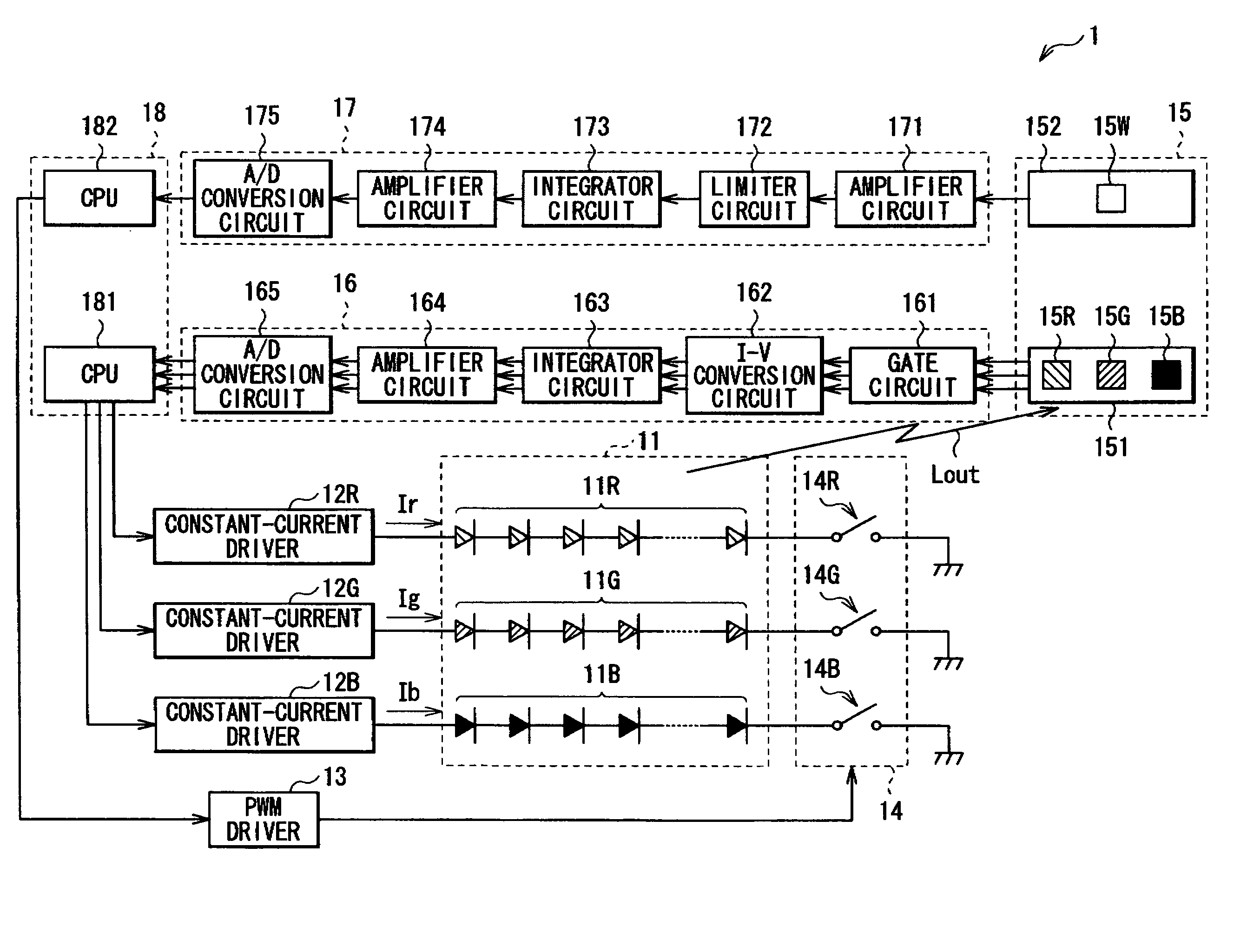
[0041]FIG. 1 shows the whole structure of an illumination system (an illumination system 1) according to a first embodiment of the invention. The illumination system 1 is an additive process illumination system obtaining a specific color light (in this case, a white light) by mixing a plurality of color lights (in this case, a red light, a green light and a blue light), and includes a light source section 11, constant-current drivers 12R, 12G and 12B and a PWM driver 13, a switch section 14, a light receiving section 15, an intensity-dependent light emission amount detecting section 16, a period-dependent light emission amount detecting section 17 and a control section 18.

[0042]The light source section 11 includes a red LED 11R, a green LED 11G and a blue LED 11B each of which includes a plurality of serial-connected LEDs.

[0043]The constant-current drivers 12R, 12G and 12B are connected to the anodes of the red LED 11R, the green LED 11G and the blue LED 11B, respectively, and...

second embodiment

[0076]Next, a second embodiment of the invention will be described below. In an illumination system according to the embodiment, the illumination area of a light source section is divided into a plurality of partial light sources. In the embodiment, like components are denoted by like numerals as of the first embodiment and will not be further described.

[0077]FIG. 9 shows a perspective view of the structure of a main part of the illumination system (an illumination system 1A) according to the embodiment. The illumination system 1A includes a light source section 11A including a plurality of partial light sources L11, L12, . . . , L21, . . . , L31, . . . arranged in a matrix form as examples of partial illumination areas, a light guide plate 191 guiding a part of the illumination light Lout from the light source 11A to the light receiving section 15 as an example of a light guide means, and a driving circuit (not shown) driving the partial light sources in order as an example of the ...


PUM


Abstract

An illumination system capable of varying the light emission intensity of illumination light while maintaining the color balance of the illumination light is provided. An additive process illumination system obtaining a specific color light by mixing a plurality of color lights, the illumination system may include a plurality of light sources each emitting a different color light; a lighting period varying means for varying the lighting period of each light source; a light emission intensity varying means for varying the light emission intensity of each light source; and a control means for controlling the lighting period varying means and the light emission intensity varying means to control the light emission amount of each light source.

Description

CROSS-REFERENCE TO RELATED APPLICATIONS[0001]This application claims priority from Japanese Patent Application No. JP 2006-149265 filed in the Japanese Patent Office on May 30, 2006, the entire content of which is incorporated herein by reference.BACKGROUND OF THE INVENTION[0002]1. Field of the Invention[0003]The present invention relates to an additive process illumination system obtaining a specific color light by mixing a plurality of color lights, and a liquid crystal display using such an illumination system.[0004]2. Description of the Related Art[0005]In recent years, flat panel displays as typified by liquid crystal TVs and plasma display panels (PDPs) have become a trend, and among them, most of mobile displays are liquid crystal displays, and precise color reproducibility is desired in the mobile displays. Moreover, as backlights for liquid crystal panels, CCFLs (Cold Cathode Fluorescent Lamps) using fluorescent tubes are mainstream; however, mercury-free light sources are ...

Claims


Application Information

Patent Timeline
Patent Type & Authority Patents(United States)
IPC IPC(8): G09G3/36G02B3/00
CPCG09G3/3413G09G3/3426G09G2360/145G09G2320/064G09G2320/0666G09G2320/0633G02F1/133
Inventor FURUKAWA, NORIMASAOKABE, MITSURUHOSHI, MITSUNARI
Owner SONY CORP
Learn More