Refrigerator with an automatic compact fluid operated icemaker

a compact fluid and refrigerator technology, applied in the field of refrigerators, can solve the problems of increasing the occurrence and severity of freezer burn, increasing the migration of sugar within products, and undesirable resistance wire approaches

Active Publication Date: 2011-10-18
WHIRLPOOL PATENTS
View PDF24 Cites 49 Cited by
  • Summary
  • Abstract
  • Description
  • Claims
  • Application Information

AI Technical Summary

Problems solved by technology

Unfortunately, this arrangement has many drawbacks.
Along with the energy concerns, the resistance wire approaches are undesirable due to their cyclic temperature loading of the freezer compartment.
The higher temperature swings of the freezer result in increased occurrences and severity of freezer burn, as well as an increase in sugar migration within products.
This cyclic high stress has a degrading effect on the plastic and causes failure of cubes to release, or even worse a breakage of the mold.
Without proper cube release, an over-fill event will occur.
With a breakage of the mold, an even worse case of continuous water flow into the product can occur until it is sensed or the consumer intervenes.
Even with devices such as ejectors and heaters to aid in the harvesting of ice cubes, ice cubes can still become stuck in a tray.
A stuck ice cube can result in an over-fill condition for the ice cube tray since the ice cube tray is typically filled with a predetermined charge of water based on the total volume of the ice cube recesses.
In an over-fill condition, the excess water will spread across the multiple ice cube recesses and, upon freezing, form a layer of ice connecting the individual ice cubes, which further increases the likelihood that the ice cubes will not be harvested.
If the icemaker has a mechanism for detecting such an over-fill condition, the icemaker is shut down until the stuck ice is removed, resulting in a loss of ice production for the consumer.
If the icemaker does not have an over-fill detection mechanism, the icemaker will continue to introduce water into the ice cube tray, which will eventually flow into the freezer to form a large block of ice, which is a great inconvenience to the consumer, especially if the ice forms on items contained within the freezer.

Method used


Image

  • Refrigerator with an automatic compact fluid operated icemaker
  • Refrigerator with an automatic compact fluid operated icemaker
  • Refrigerator with an automatic compact fluid operated icemaker

Examples


Embodiment Construction

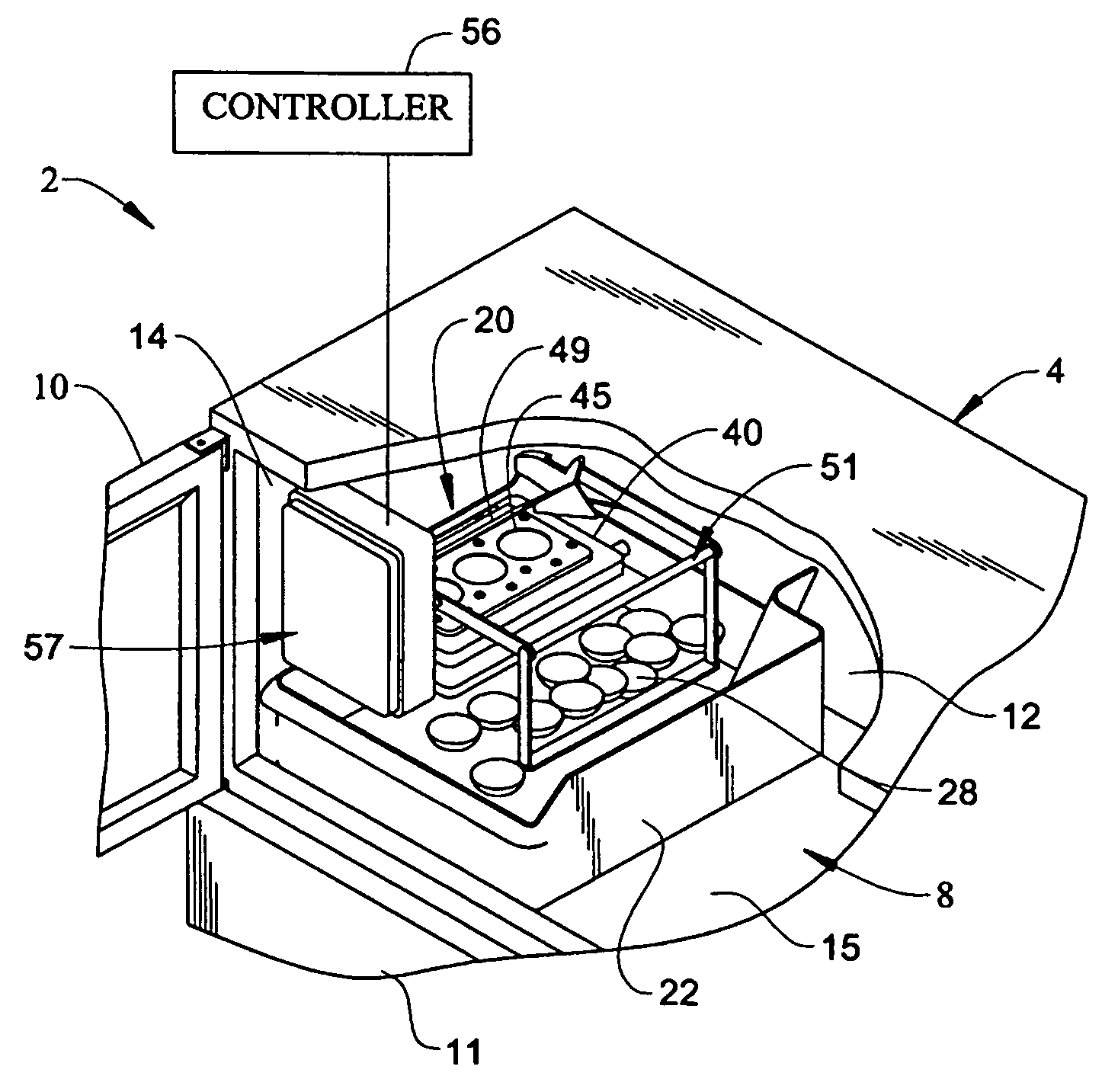
[0021]With initial reference to FIG. 1, a refrigerator, generally indicated at 2, includes a cabinet 4 having arranged therein a freezer compartment 8 which can be selectively accessed through the pivoting of a freezer door 10. Also provided is a fresh food door 11 which enables access to a fresh food compartment (not separately labeled). As shown, the refrigerator 2 constitutes a top mount style unit. However, as will become more fully evident below, the present invention is equally applicable to various other types of refrigerators, including side-by-side style units, bottom mount units and French door units.

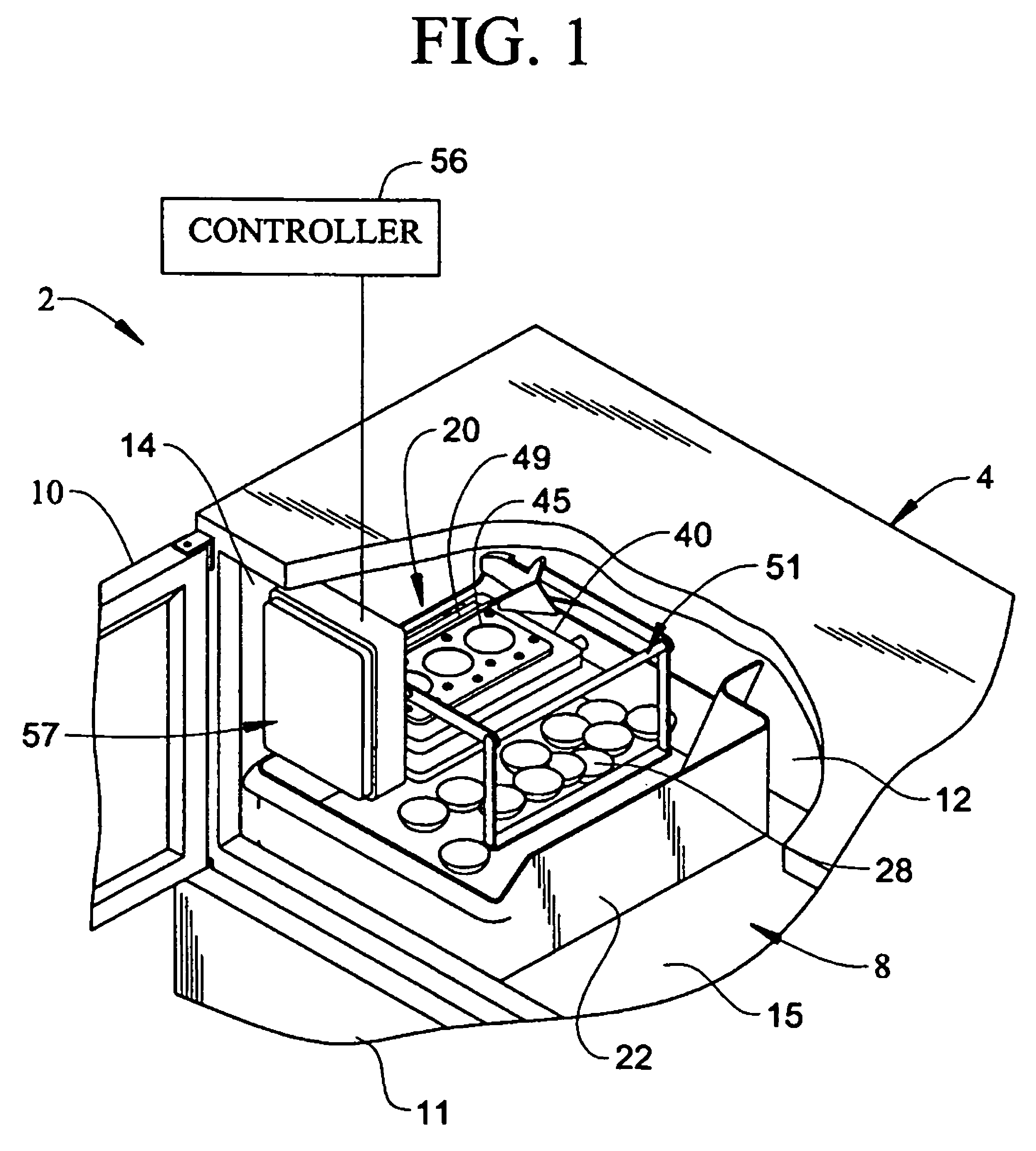
[0022]The freezer compartment 8, as depicted in FIG. 1, shows a back wall 12, a side wall 14 and a bottom wall 15. An automatic compact icemaker 20 is located within the freezer compartment 8 and is preferably mounted to the side wall 14 of the freezer compartment 8. An ice cube bin 22 rests on the bottom wall 15 of the freezer compartment 8 and is located beneath the icemaker...


PUM


Abstract

An icemaker for a refrigerator having a cabinet with a refrigerated compartment and an unrefrigerated machine compartment includes a body portion formed with an inlet, an outlet and an opening. A flexible mold is positioned in the opening. A water supply is positioned to provide water to the flexible mold. A fluid supply circuit, including a pump mounted in the machine compartment, a first fluid conduit connected between the pump and the inlet, and a second fluid conduit connected to the outlet, provides warm fluid to the body portion. The icemaker forms ice during an ice production cycle and the fluid warmed in the machine compartment is used to partially melt and aid in releasing the ice which is then deposited in a ice storage bin during a harvest cycle.

Description

BACKGROUND OF THE INVENTION[0001]1. Field of the Invention[0002]The present invention pertains to the art of refrigerators and, more particularly, to an automatic compact fluid operated icemaker arranged within a refrigerator.[0003]2. Description of the Related Art[0004]Household refrigerator / freezers are commonly sold with an icemaker, which is a great convenience to the consumer. Icemakers can be generally categorized into two classes based on the manner in which the ice is harvested from the ice cube tray. The most common method is for the ice to be formed in an ice cube tray incorporating multiple ejectors that forcibly eject the ice from ice cube recesses in the ice cube tray, typically defined by a metal mold. The other class of icemakers has ice cube trays that are inverted to expel the ice cubes from the ice cube recesses of the ice cube tray. These icemakers are usually made from a plastic material and are generally referred to as flextrays.[0005]In the metal mold class of ...

Claims


Application Information

Patent Timeline
Patent Type & Authority Patents(United States)
IPC IPC(8): F25C5/06F25C1/00A23G9/00
CPCF25C5/08F25C5/06F25C2700/12F25C2600/04F25C2400/10
Inventor LECLEAR, DOUGLAS DAVIDTENBARGE, ANDREW MICHAELWU, GUOLIANTROMBLEE, JON DONALD
Owner WHIRLPOOL PATENTS
Why Eureka
Try Eureka