Eureka AIR delivers breakthrough ideas for toughest innovation challenges, trusted by R&D personnel around the world.

Fresnel zone imaging system and method

a technology of ultrasound imaging and ultrasound zone, applied in the field of imaging systems, can solve the problems of reducing image resolution and contrast, undesirable sidelobes,

Active Publication Date: 2011-10-18
GENERAL ELECTRIC CO
View PDF23 Cites 19 Cited by
  • Summary
  • Abstract
  • Description
  • Claims
  • Application Information

AI Technical Summary

Problems solved by technology

Sidelobes are usually undesirable as they reduce both image resolution and contrast.
Firstly, it allows larger groupings of elements to use a single time delay.
Secondly, especially in optical or similar narrow-band systems, one specific time delay for all constructive zones is used and a different time delay is used for all destructive zones.
One problem with the above described method in which the weighting of the various regions of the transducer is restricted to the values +1 and −1 is the generation of radiation patterns with a certain sidelobe level.

Method used


Image

  • Fresnel zone imaging system and method
  • Fresnel zone imaging system and method
  • Fresnel zone imaging system and method

Examples


Embodiment Construction

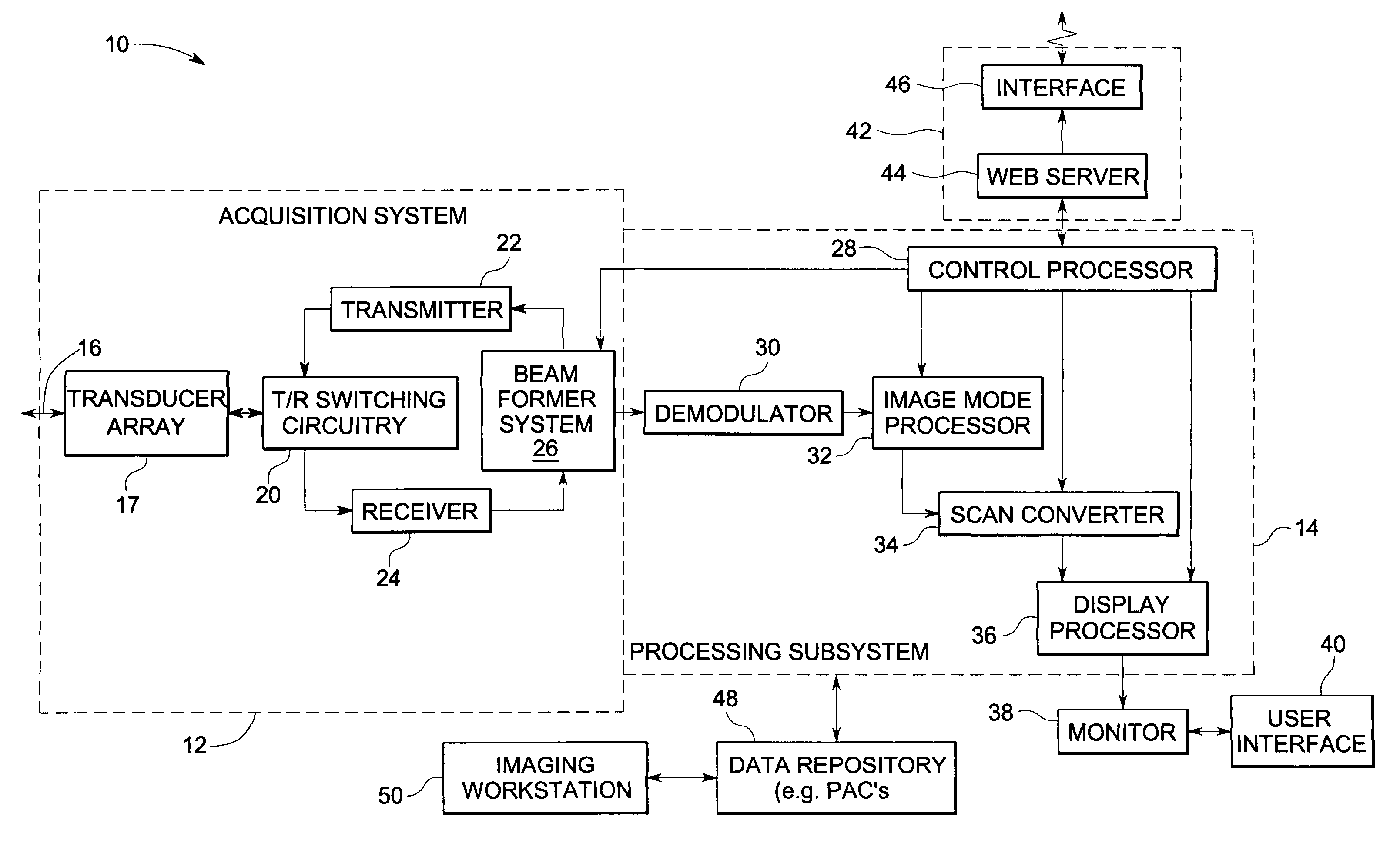
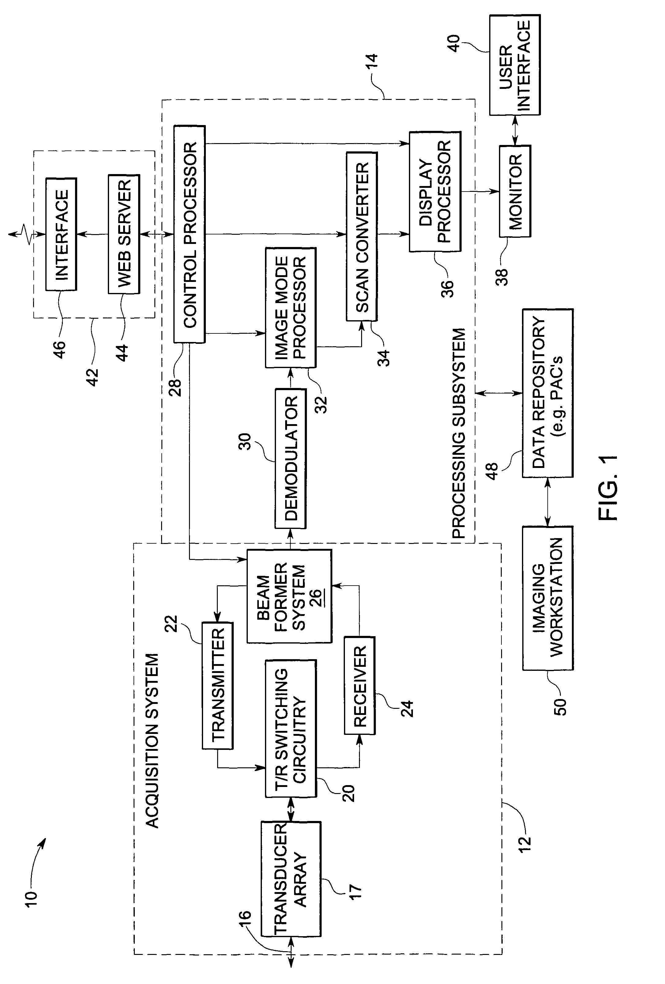
[0023]FIG. 1 is a block diagram of an embodiment of an ultrasound system 10 using Fresnel zone imaging methods. It may be appreciated that the ultrasound system of FIG. 1 is shown by way of example only. Fresnel zone imaging techniques may also be used in other imaging systems such as radar systems, sonar systems and optical systems.

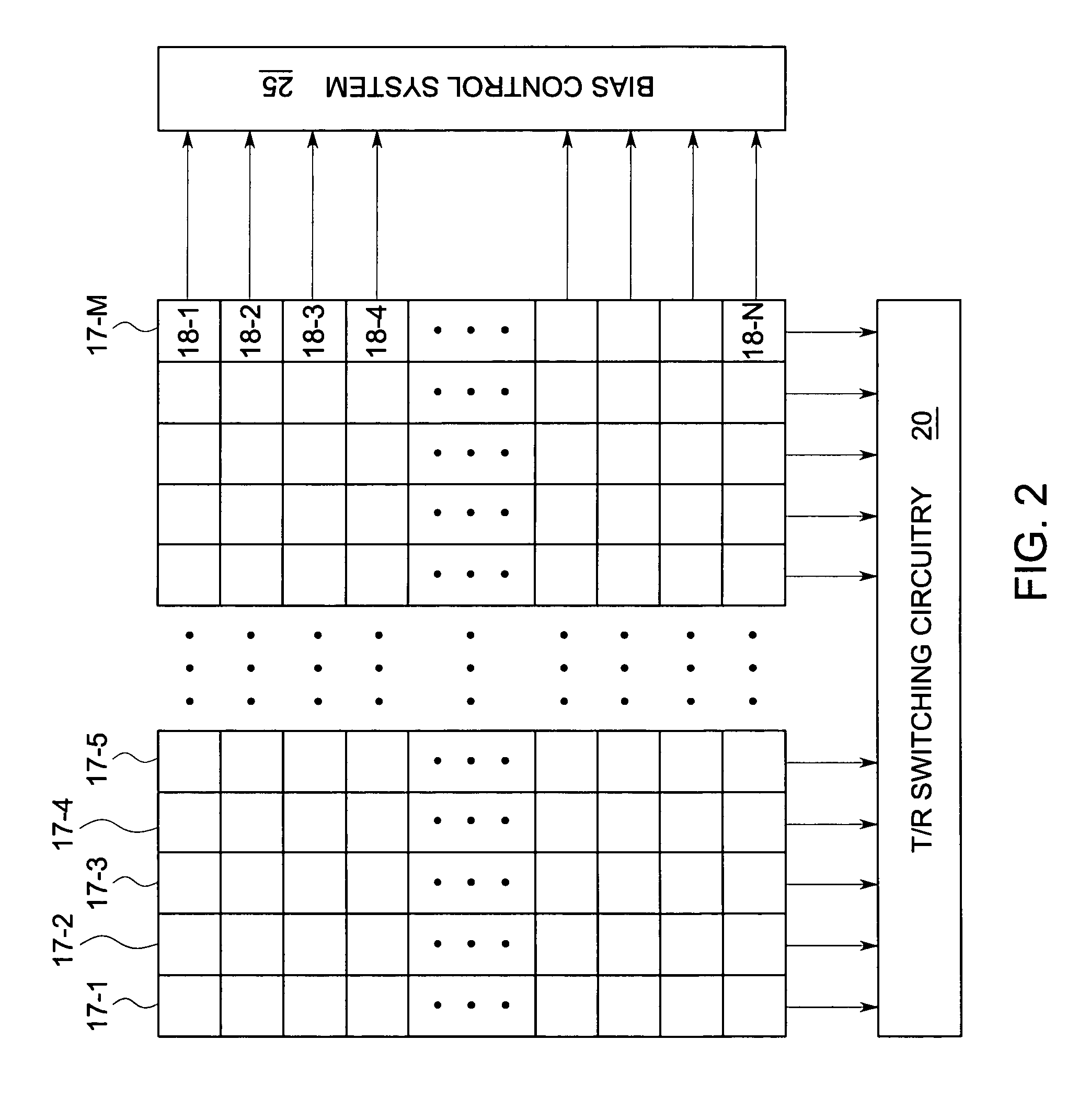
[0024]The ultrasound system comprises acquisition subsystem 12 and processing subsystem 14. The acquisition subsystem 12 comprises an energy transmitting device, transmit / receive switching circuitry 20, a transmitter 22, a receiver 24, and a beamformer 26. Fresnel zone imaging is used in the acquisition subsystem that enables the focussing of the ultrasound beam in a desired direction. In the illustrated embodiment, the energy transmitting device is a transducer array 17 composed of a plurality of transducer elements 17-1 through 17-M.

[0025]Processing subsystem 14 comprises a control processor 28, a demodulator 30, an imaging mode processor 32, a scan co...


PUM


Abstract

A method for Fresnel zone imaging is provided. The method comprises identifying a plurality of constructive regions and a plurality of destructive regions in an energy transmitting device and converting the destructive regions to the constructive regions by using an apodization profile. The apodization profile comprises apodization values for each constructive region and destructive region and the apodization values comprise real numbers.

Description

BACKGROUND[0001]The present invention relates generally to imaging systems, and specifically to Fresnel zone imaging methods in ultrasound imaging systems.[0002]Ultrasound imaging is usually achieved through the use of a transducer array, which is composed of multiple individually addressable elements that are activated in such a way as to form an acoustic beam (beamforming). The beam is of a certain shape and is directed towards specific locations in the imaging medium that suit the particular imaging configuration. The transducer array receives back scattered signals from the imaging medium which are then used to create an ultrasound image.[0003]In most imaging applications, image quality is an important parameter. Typically, image quality metrics include spatial resolution and contrast resolution. Image quality, including resolution and contrast, is directly related to the acoustic beam characteristics. Characteristics of the acoustic beam are in turn determined by the physical p...

Claims


Application Information

Patent Timeline
Patent Type & Authority Patents(United States)
IPC IPC(8): A61B8/00G01S15/00
CPCA61B8/00
Inventor LEE, WARRENRIGBY, KENNETH WAYNESMITH, LOWELL SCOTT
Owner GENERAL ELECTRIC CO
Why Eureka
Eureka Blog
Learn More