
Sternotomy splinting assembly, kit and method for use

a sternotomy and kit technology, applied in the field of sternotomy splinting assembly, can solve the problems of over-complex devices, significant pain associated with sternal healing, and difficulty in minimizing patient pain, so as to reduce pain, promote healing, and reduce the effect of patient pain

Inactive Publication Date: 2011-10-18
ROLNICK MICHAEL A +2
View PDF13 Cites 5 Cited by
  • Summary
  • Abstract
  • Description
  • Claims
  • Application Information

AI Technical Summary

Benefits of technology

"The present invention provides an assembly, kit, and method for splinting a sternotomy that can provide a continuous, adjustable, and compressive tangential stabilizing force to the ribcage to promote healing while minimizing patient pain. The assembly includes two anchor patches placed on the chest wall and elastomeric straps placed across the site. The elastomeric straps can be removably affixed to the anchor patches and have a spring-constant that can be adjusted to create a reducing force profile that maximizes patient comfort. The elastomeric straps can be reapplied and adjusted for maximum comfort. A pad can be placed between the elastomeric straps and the chest wall to produce a force normal to the chest wall at the sternotomy site. The kit includes the necessary elements for splinting a sternotomy incision and can optionally include a solvent for easy removal of the anchor patches. The invention provides a more effective and comfortable method for splinting a sternotomy incision."

Problems solved by technology

While it is sometimes possible to use less invasive surgical techniques, many of these procedures require gaining access by opening up the chest at the breastbone.
There is significant pain associated with sternal healing.
The necessary coughing and deep breathing are frequently very painful following sternotomy.
However, these devices are overly complex and can be painful to apply and adjust on patients who are elderly, obese or have dementia.
However, this device too is deficient as the tangential force is not applied to the ribcage continuously but rather is applied by the patient as necessary, by pulling the handle portions toward each other so as to decrease the frontal gap.
The device is well suited to patients with good arm strength, but may not be suitable for patients who are obese, elderly, have dementia, or are incapable of grasping and applying force to the handle portions.

Method used


Image

  • Sternotomy splinting assembly, kit and method for use
  • Sternotomy splinting assembly, kit and method for use
  • Sternotomy splinting assembly, kit and method for use

Examples


examples

[0037]Hereinafter, the present invention is described in more detail by reference to the exemplary embodiments. However, the following examples only illustrate aspects of the invention and in no way are intended to limit the scope of the present invention. As such, embodiments similar or equivalent to those described herein can be used in the practice or testing of the present invention.

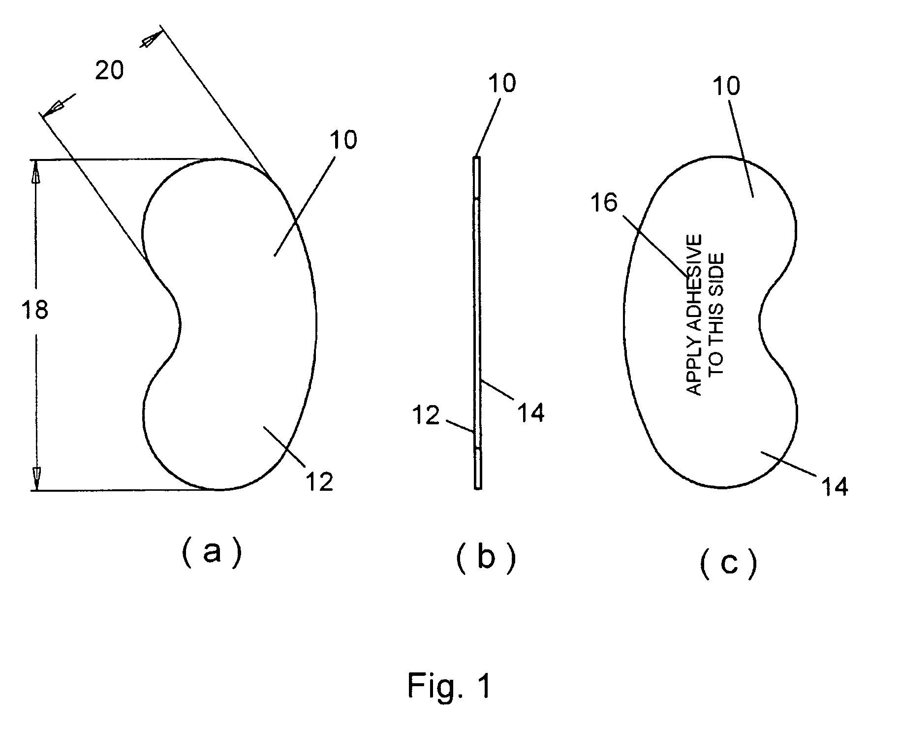
[0038]Referring now to the figures, FIGS. 1a through 1c depict a first embodiment of an anchor patch 10 suitable for use in conjunction with a sternotomy splinting system of the present invention. Patch 10 has a first side 12, an obverse surface, having formed thereon hooks or hook protrusions suitable for forming a hook and loop fastener pair, and a second side 14, a reverse surface, having an indicia 16 formed thereon, indicia 16 indicating that second side 14 is the side to which adhesive should be applied. Patch 10 has a contoured or curvilinear shape, the length 18 of patch 10 preferably between...


PUM


Abstract

Herein disclosed is a simple, passive splinting system for sternotomy patients designed to provide a continuous yet readily adjustable, compressive tangential stabilizing force to the ribcage so as to promote healing of a median sternotomy incision while minimizing patient pain.

Description

PRIORITY[0001]This application claims the benefit of U.S. Provisional Application No. 61 / 008,764 filed Dec. 21, 2007, the entire contents of which are incorporated by reference herein.FIELD OF THE INVENTION[0002]The present invention relates to a splinting assembly, kit and method. More particularly, the present invention relates to an assembly, method and kit for splinting a median sternotomy incision on a patient post-surgery.BACKGROUND OF THE INVENTION[0003]Patients undergo chest surgery for a variety of reasons including coronary artery bypass, tumor removal, lung and heart transplants. While it is sometimes possible to use less invasive surgical techniques, many of these procedures require gaining access by opening up the chest at the breastbone. There are three basic incisions used to gain access: full sternotomy, partial sternotomy and thoracotomy. The type of incision used depends on the procedure and the general health of the patient. The most common incision is a full ster...

Claims


Application Information

Patent Timeline
Patent Type & Authority Patents(United States)
IPC IPC(8): A61F5/00A61B17/84
CPCA61B17/085A61B19/026A61B17/823A61B2017/081A61B50/30Y10S607/902
Inventor ROLNICK, MICHAEL A.WARDEN, MATTHEW P.VAN WYK, ROBERT A.
Owner ROLNICK MICHAEL A
Learn More