Wind turbine generator and method of controlling the same

a technology of wind turbine generator and wind turbine blade, which is applied in the direction of electric generator control, machines/engines, mechanical equipment, etc., can solve the problems of inability to perform desired operation, apparatus cannot operate regardless, and the wind turbine blade cannot rotate, so as to reduce the stop time of the wind turbine generator

Inactive Publication Date: 2011-10-18
MITSUBISHI HEAVY IND LTD
View PDF8 Cites 9 Cited by
  • Summary
  • Abstract
  • Description
  • Claims
  • Application Information

AI Technical Summary

Benefits of technology

[0006]The present invention is achieved to solve the above problem, and it is an object thereof to provide a wind turbine generator reducing stop time of the wind power turbine generator due to icing on wind turbine blades, as well as a method of controlling the same.
[0009]Hitherto, in a case where icing occurs, the operation is immediately stopped. For example, when the stop period continues for a long period, devices in the wind turbine are cooled, so that a problem occurs that it takes considerably long time to restart the apparatus. On the contrary, in the present invention, even when icing is detected, the operation is continued in the no-load operation mode as described above. Therefore, warm-up can be continuously performed. For example, in a case where the icing amount decreases during the no-load operation mode and the operation is then restarted, the operation can be restarted from a state where the devices are warmed. Thus, the time required for operation restart can be shortened.
[0011]With such a configuration, in the case where the icing amount is larger than the first predetermined value and is equal to or less than the second predetermined value, the operation is performed in the no-load operation mode. When the icing amount exceeds the second predetermined value, the operation is stopped. For example, in a case where a threshold as an icing amount which affects the operation of the wind turbine generator is set as the second predetermined value, the operation in the no-load operation mode can be continuously performed as long as the operation of the wind turbine generator is not affected. The opportunity of restarting the operation from the warm-up state can be increased.
[0013]As described above, in the case where the icing amount is below the third predetermined value which is set to be equal to or less than the first predetermined value in the state where the apparatus is operated in the no-load operation mode, the mode is switched from the no-load operation mode to the normal operation mode. Even in the case where the icing amount becomes larger than the first predetermined value once, the mode is reset to the normal operation upon decrease in the icing amount. Therefore, decrease in work rate of the wind turbine generator can be prevented. By providing with a hysteresis each of the condition for switching the mode from the normal operation to the no-load operation and the condition for switching the mode from the no-load operation to the normal operation, operation control can be stabilized.
[0015]As described above, in the no-load operation mode, the rotational speed of the wind turbine rotor is set so that ice adhering to the wind turbine blade does not reach a wind turbine generator in the neighborhood. It can prevent influence on the neighborhood of the flying ice which adheres to the wind turbine blade.
[0021]According to the present invention, there is exerted an effect of reducing stop time of the wind turbine generator due to icing on a wind turbine blade.

Problems solved by technology

Consequently, the wind turbine blade does not rotate and desired operation cannot be performed.
However, conventionally, in a case where icing occurs before start of a wind turbine generator, the apparatus does not operate regardless of the degree of icing.
It takes time to start the wind turbine generator and there is a problem that the work rate of the wind turbine generator decreases.

Method used


Image

  • Wind turbine generator and method of controlling the same
  • Wind turbine generator and method of controlling the same
  • Wind turbine generator and method of controlling the same

Examples


Embodiment Construction

[0034]An embodiment of a wind turbine generator according to the present invention will be described below with reference to the drawings.

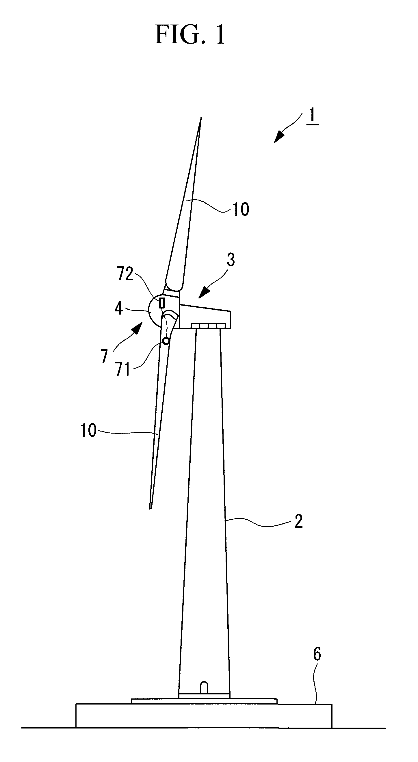
[0035]FIG. 1 is a schematic diagram showing a schematic configuration of a wind turbine generator 1 according to the present embodiment.

[0036]As shown in FIG. 1, the wind turbine generator 1 includes a support 2, a nacelle 3 provided on the upper end of the support 2, and a rotor head 4 provided to the nacelle 3 so as to be rotatable about an almost horizontal axis. To the rotor head 4, three wind turbine blades 10 are radially attached about the rotational axis of the rotor head 4. With the configuration, a force of wind hitting the wind turbine blade 10 from the rotational axis direction of the rotor head 4 is converted to power for rotating the rotor head 4 about the rotational axis, and this power is converted to electric energy by a generator provided to the wind turbine generator 1.

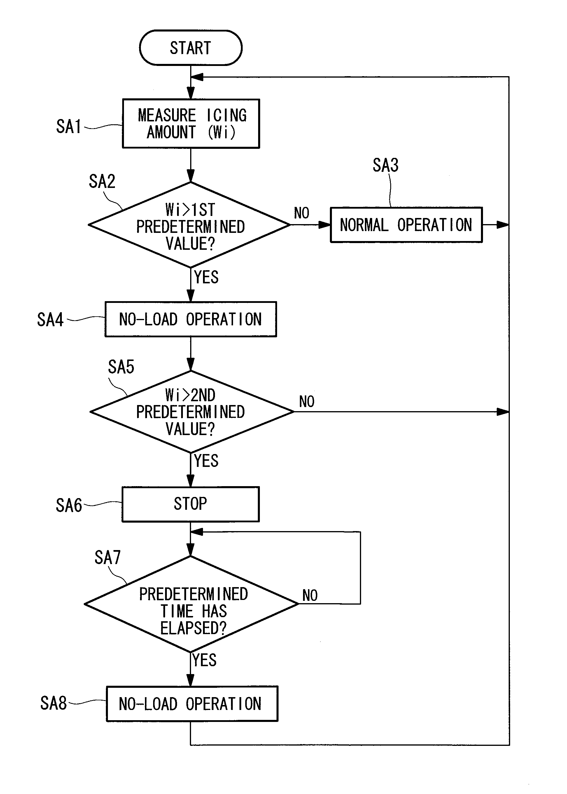
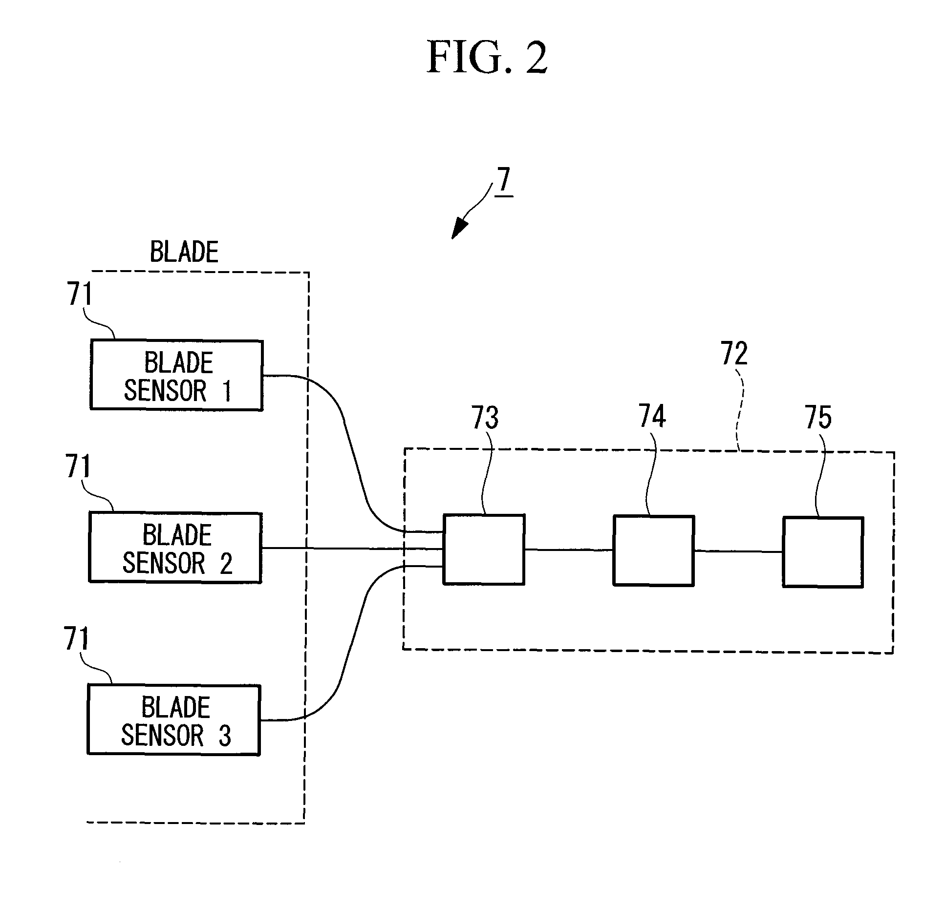
[0037]The wind turbine generator 1 also includes an ice dete...


PUM


Abstract

An object of the invention is to reduce stop time of a wind turbine generator caused by icing on a wind turbine blade in the wind turbine generator. The invention provides the wind turbine generator including an ice detecting unit for detecting an amount of icing on a wind turbine blade, wherein an operation mode is switched to a no-load operation mode with no power being generated in a case where the icing amount detected by the ice detecting unit exceeds a first predetermined value, and an icing amount is detected by the ice detecting unit in a state where the apparatus is operated in the no-load operation mode.

Description

RELATED APPLICATIONS[0001]The present application is a national phase of, and claims priority from, International Application Number PCT / JP2009 / 061727, filed Jun. 26, 2009, the disclosure of which is hereby incorporated by reference herein in its entirety.TECHNICAL FIELD[0002]The present invention relates to a wind turbine generator and a method of controlling the same.BACKGROUND ART[0003]Conventionally, there is known a wind turbine generator for generating power by using a force of wind as natural energy. In such a wind turbine generator, as the outside air temperature decreases, supercooled water droplets, moisture, or the like in the air collide with wind turbine blades and the like to be frozen, thereby causing icing on the wind turbine blades and the like. For example, Patent Citation 1 discloses a method of detecting icing on a wind turbine generator.Patent Citation 1: U.S. Pat. No. 7,086,834DISCLOSURE OF INVENTION[0004]Icing tends to occur mostly in the front edge part of a ...

Claims


Application Information

Patent Timeline
Patent Type & Authority Patents(United States)
IPC IPC(8): F03D7/04
CPCF03D7/0264F03D7/0276F03D7/042F03D11/0025Y02E10/722F05B2260/80Y02E10/723F03D80/40Y02E10/72
Inventor MIZOUE, TAKETOBABA, MITSUYAHAYASHI, YOSHIYUKI
Owner MITSUBISHI HEAVY IND LTD
Why Eureka
Try Eureka