
Automatic ice making machine and operation method therefor

a technology ice making machine, which is applied in the field of automatic ice making machine, can solve the problems of increasing the amount of water consumed, and achieve the effects of preventing the deicing cycle from becoming longer, suppressing and reducing the amount of consumed water

Inactive Publication Date: 2011-10-25
HOSHIZAKI ELECTRIC CO LTD
View PDF16 Cites 11 Cited by
  • Summary
  • Abstract
  • Description
  • Claims
  • Application Information

AI Technical Summary

Benefits of technology

The present invention relates to an automatic ice making machine that can efficiently deice ice blocks without wasting a large amount of deicing water and preventing damage to the machine. The invention proposes an operation method for the machine that supplies deicing water to the ice making unit in a continuous and intermittent manner during the deicing cycle. By doing so, the machine can prevent stains from adhering to the ice making unit and overheating of the machine, which can lead to damage or reduced ice making performance. The intermittent supply of deicing water also helps to accelerate the separation of ice blocks, reducing the deicing time.

Problems solved by technology

If the deicing water is kept supplied until the deicing cycle is completed, therefore, a large amount of deicing water is discharged wastefully, increasing the amount of water consumed.

Method used


Image

  • Automatic ice making machine and operation method therefor
  • Automatic ice making machine and operation method therefor
  • Automatic ice making machine and operation method therefor

Examples


first embodiment

Operation of First Embodiment

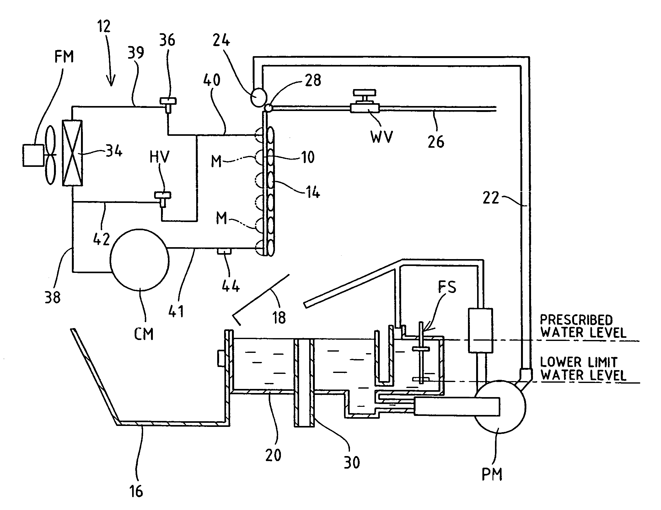
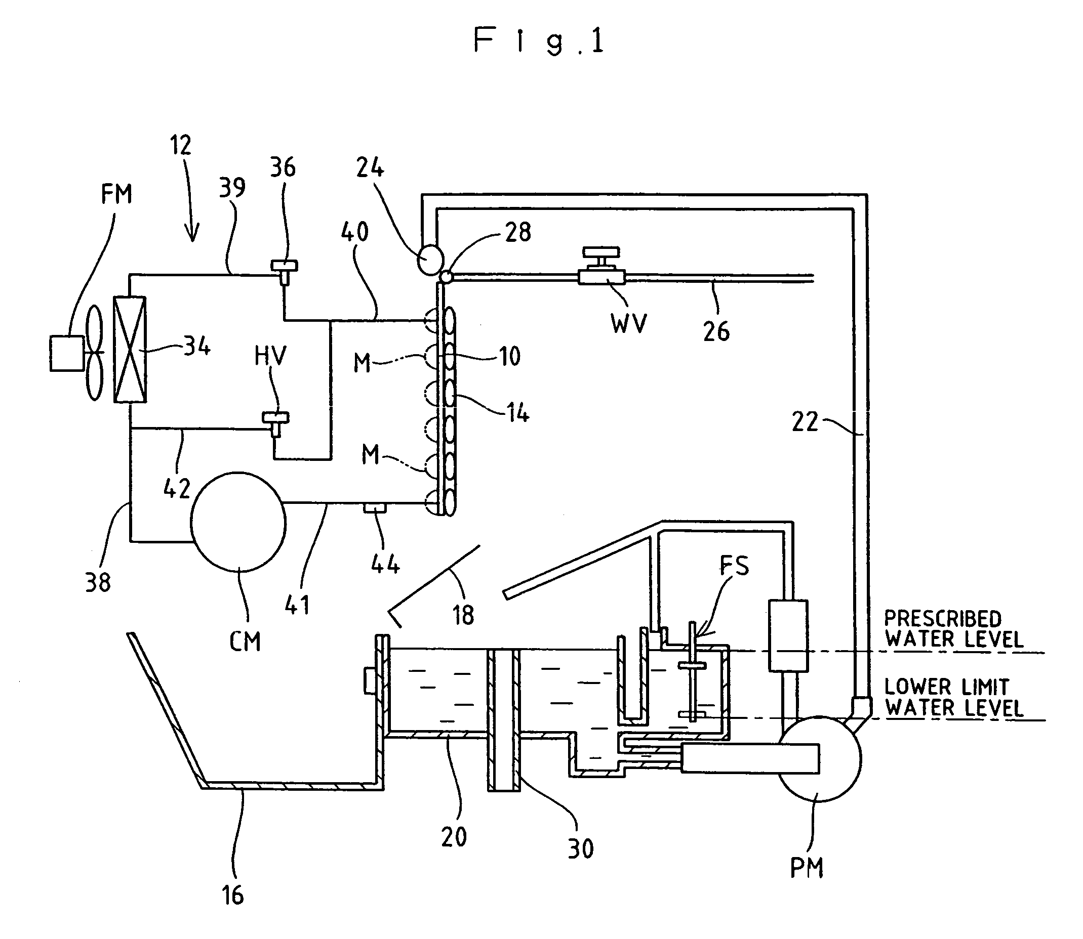
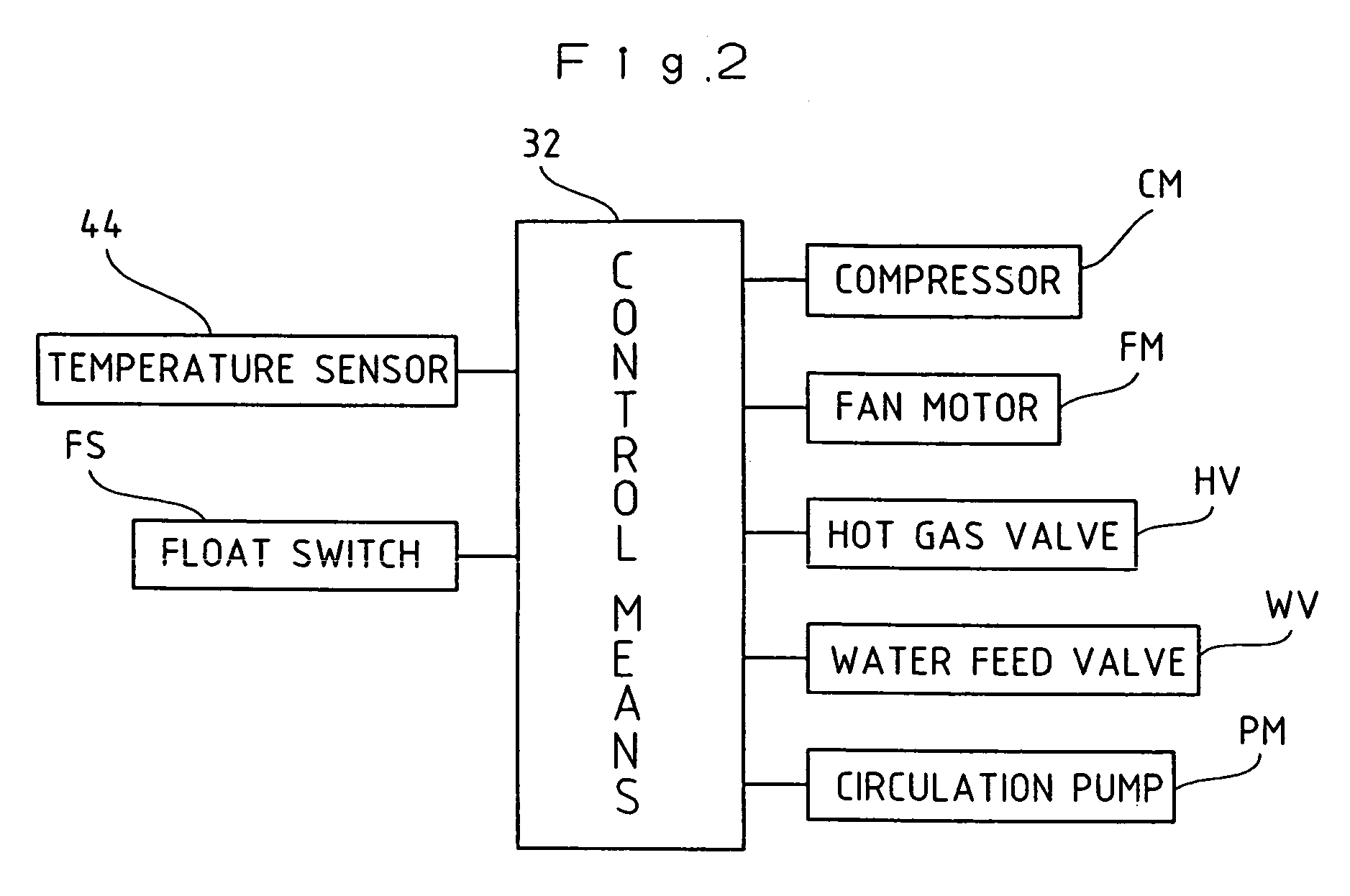
[0040]Next, the operation of the automatic ice making machine according to the first embodiment will be described in conjunction with the operation method referring to a timing chart shown in FIG. 3. At the time of the ice making cycle, a refrigerant is circulatively supplied to the evaporation tube 14 disposed at the back surface of the ice making plate 10 to cool down the ice making plate 10. Further, the operation of the circulation pump PM causes the ice making water from the ice-making water tank 20 to be pumped out to the ice-making water sprayer 24 to be sprayed onto the ice making surface of the ice making plate 10 through the individual spray holes of the ice-making water sprayer 24. At the time the ice making cycle starts, the ice making water is stored in the ice-making water tank 20 to the prescribed water level prescribed by the overflow tube 30, and the float switch FS is in the ON state.

[0041]The ice making plate 10 exchanges heat with the...

second embodiment

Operation of Second Embodiment

[0051]Next, the operation of the automatic ice making machine according to the second embodiment will be described in conjunction with the operation method referring to a timing chart shown in FIG. 5. A description on the same operation as that of the first embodiment will be omitted.

(When the automatic ice making machine is new and the deicing cycle is completed in an allowable time)

[0052]When the deicing cycle progresses to separate ice blocks M from the ice making plate 10, and the temperature of the hot gas rises so that the temperature sensor 44 detects the deicing completion temperature, the deicing completion delay timer TM starts measuring the time. When the outside temperature is high or when the ice making surface of the ice making plate 10 does not have upheavals originated from time-dependent degradation so that separation of ice blocks M is carried out smoothly, the temperature sensor 44 detects the deicing completion temperature before the...


PUM


Abstract

To restrict the deposition of stain on an ice making unit, and prevent damage to resin components or the like. The above problems are solved by the followings. Ice making water is supplied to the front surface of an ice making plate cooled by refrigerant supplied to an evaporation tube during an ice making cycle to produce ice blocks. During a deicing cycle, deicing water is supplied by opening a water feed valve WV to the rear surface of the ice making plate to be heated by hot gas supplied to the evaporation tube. When a water feed time has elapsed, the water feed valve WV is closed to temporarily stop deicing water supply. After the water feed time elapsed, a cycle, in which the water feed valve WV is opened as much as an intermittent water supply time every time an intermittent stopping time has elapsed to intermittently supply deicing water, is repeated until a deicing cycle completes.

Description

TECHNICAL FIELD[0001]The present invention relates to an automatic ice making machine which supplies deicing water to an ice making unit heated by heating means to separate ice blocks produced by the ice making unit at the time of a deicing cycle, and an operation method for the automatic ice making machine.BACKGROUND ART[0002]As an ice making machine that automatically makes ice blocks, there is known a down flow type ice making machine in which an evaporation tube constituting a freezing system is arranged in a meandering manner at the rear surface of an ice making plate disposed approximately vertically, and ice making water is let to flow down the top surface of the ice making plate at the time a refrigerant is circulatively supplied to the evaporation tube to cool the ice making plate at the time of an ice making cycle, after which the cycle goes to a deicing cycle to separate and drop the ice blocks from the ice making plate.[0003]At the time of the deicing cycle of the down f...

Claims


Application Information

Patent Timeline
Patent Type & Authority Patents(United States)
IPC IPC(8): F25C1/00
CPCF25C1/12F25C5/10F25C2400/12F25C2400/14
Inventor MORIMOTO, RYOJITAKAGI, TOMOHIRO
Owner HOSHIZAKI ELECTRIC CO LTD
Learn More