Arrangement for measuring a rate of rotation using a vibration sensor

a technology of vibration sensor and rate of rotation, which is applied in the direction of acceleration measurement using interia force, turn-sensitive devices, instruments, etc., can solve the problems of considerable interference in the output signal to be determined the rate of rotation, impair the measurement accuracy, etc., and achieve the effect of reducing the interference caused by the excitation voltag

Inactive Publication Date: 2011-10-25
CONTINENTAL AUTOMOTIVE GMBH +1
View PDF19 Cites 9 Cited by
  • Summary
  • Abstract
  • Description
  • Claims
  • Application Information

AI Technical Summary

Benefits of technology

As a result, the charge currents at the fixed connection are compensated for, whereas the drive torques generated are intensified since the drive torques are proportion...

Problems solved by technology

In this case, the amplitude of the AC voltage supplied to the drive is considerably greater than that of the signals obtained from the change in capacitance, with the result th...

Method used


Image

  • Arrangement for measuring a rate of rotation using a vibration sensor
  • Arrangement for measuring a rate of rotation using a vibration sensor
  • Arrangement for measuring a rate of rotation using a vibration sensor

Examples


Embodiment Construction

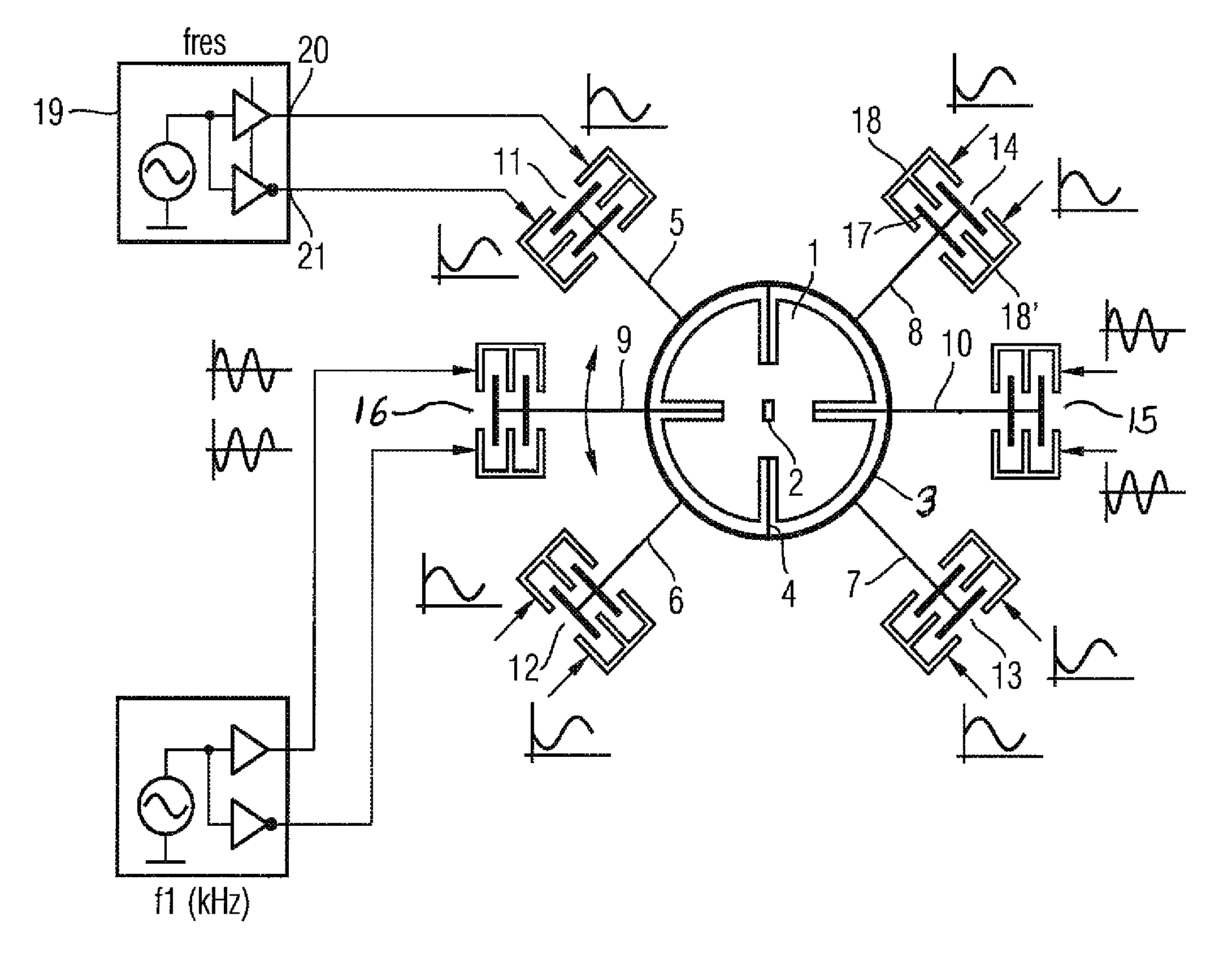
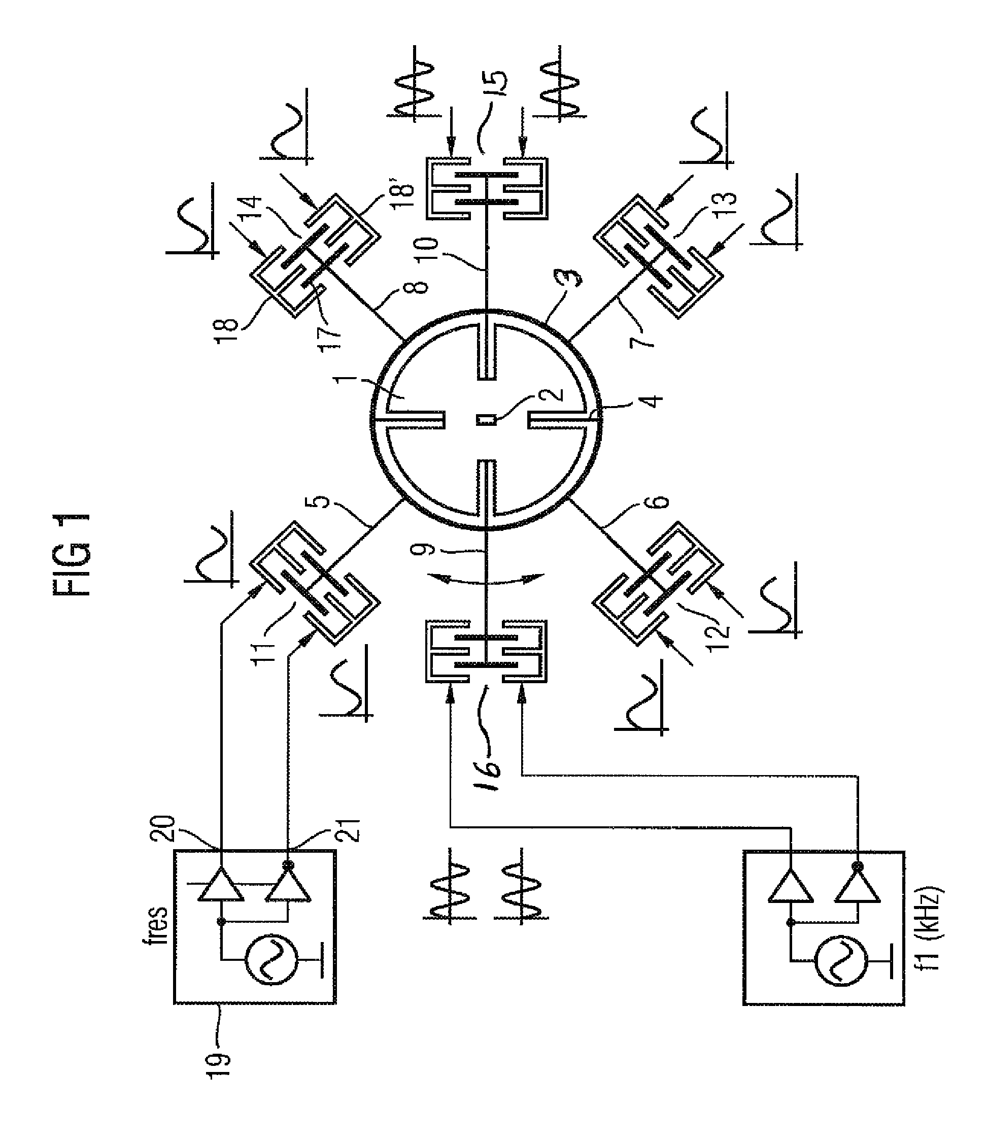
The vibrational gyroscope illustrated in FIG. 1 comprises a disk 1 which is mounted such that it can be tilted at 2 but cannot be rotated. A ring 3 is connected to the disk 1 via resilient tongues 4 in such a manner that it can be made to vibrate rotationally with respect to the disk 1.

A plurality of arms 5 to 10 having capacitive elements 11 to 16 are situated on the circumference of the ring 3. In the schematic illustration according to FIG. 1, the arms 5 to 10 are illustrated in lengthened form in comparison with an exemplary embodiment. The capacitive elements 11 to 16 each comprise electrodes 17, which are arranged on the arm and can therefore be moved with the ring 3, and fixed electrodes 18, 18′.

The fixed electrodes 18, 18′ are applied, such that they are insulated, to a substrate (not illustrated) that integrally includes elements 1 to 17. Methods for patterning the substrate are known in the art and do not need to be discussed in any more detail in connection with the inven...


PUM


Abstract

An arrangement for measuring a rate of rotation using a vibration sensor, being excited and measured by means of capacitive drive elements, and the rotation of said sensor in an axis, excited by a rotation in another axis by means of the Coriolis force, being measured by means of capacitive measuring elements. Excitation voltages can be supplied to the fixed electrodes of the drive elements, the frequency of said voltages corresponding to the resonance frequency or the subharmonic of the resonance frequency of the vibration sensor. An alternating voltage having a first measuring frequency which is higher than the excitation frequency can be supplied to capacitive elements for measuring the excited vibration. Alternating voltages having a second measuring frequency higher than the excitation frequency are supplied to the fixed electrodes of the measuring elements can be supplied to drive elements causing a vibration excitation in a direction on the basis of the excitation voltage, being in antiphase with the excitation voltage.

Description

PRIORITY CLAIMThis is a U.S. national stage of application No. PCT / EP2007 / 059607, filed on 13 Sept. 2007, which claims priority to the German Application No.: 10 2006 046 772.8, filed: 29 Sept. 2006; the contents of both being incorporated herein by reference.BACKGROUND OF THE INVENTION1. Field of the InventionThe invention relates to an arrangement for measuring a rate of rotation using a vibration sensor. Vibration that is perpendicular to a first axis is excited and measured with the aid of capacitive drive elements, and the rotation about a second axis, which is excited by rotation in a third axis under the action of the Coriolis force, is measured with the aid of capacitive measuring elements, the capacitive elements each being formed by fixed electrodes and by electrodes which can be moved with the vibration sensor, the movable electrodes being jointly connected to a fixed connection.2. Description of Prior ArtRate of rotation sensors are used, for example, in safety systems f...

Claims


Application Information

Patent Timeline
IPC IPC(8): G01C19/56
CPCG01C19/5712G01C19/56
Inventor GIER, LOTHARKEMPE, VOLKERSTRLE, DRAGO
Owner CONTINENTAL AUTOMOTIVE GMBH
Why Eureka
Try Eureka