Vapour-liquid distribution device

a technology of liquid distribution device and trough, which is applied in the direction of combustion air/fuel air treatment, separation process, carburetor air, etc., can solve the problems of uneven liquid distribution over the surface below the tray, mechanical complexity of the known trough type distribution device, and high levelness, so as to improve the wetting efficiency. below the tray, the effect of reducing the pitch

Active Publication Date: 2011-10-25
TOPSOE AS
View PDF15 Cites 4 Cited by
  • Summary
  • Abstract
  • Description
  • Claims
  • Application Information

AI Technical Summary

Benefits of technology

[0018]The vapour lift tube device according to the invention is similar to the bubble cap device in concept but has several advantages. Since the vapour lift tube device is smaller, more can be placed on a distribution tray being made by arranging a number of beams side by side inside a reactor to achieve better distribution of liquid. With a smaller spacing, the size of these gaps is smaller. Overall wetting efficiency below the tray is better with a smaller pitch than with a larger pitch.
[0019]A particular advantage of the distribution device according to the invention is its simplicity that makes it easier and less costly to fabricate and to install in the optimal size proscribed by process conditions.
[0020]In many processes where the invention will be used, e.g. hydroprocessing reactors, there can be wide variations in the vapour and liquid phase rates and physical properties over time and during turndown operations. Due to fabricating tolerances and the care of installation, there will be unavoidable variations in the distribution tray levelness. Liquids dropping onto the distribution tray from an inlet distributor or quench zone mixer may be unevenly distributed and could result in liquid height gradients across the tray due to splashing, waves or hydraulic head. An optimized liquid distributor design using the vapour lift tube concept is possible that will provide better liquid distribution below the tray than can be obtained from optimized designs of trough distributors, simple perforated plate distribution trays, chimney type distribution trays or concentric bubble cap distribution trays.
[0021]The distribution device of this invention will typically be used in hydroprocessing reactors. By obtaining even distribution of the liquid reactants over the entire reactor cross sectional area, all the catalyst at a given level is evenly wetted. Thus, all the catalysts at a given level operate at the same efficiency, which increases the overall efficiency of the reactor. Additionally, even liquid distribution maintains even radial temperature profiles across the reactor.

Problems solved by technology

The known trough type distribution device is mechanically complex and very sensitive to levelness.
Depending on the design of the transitions between troughs, the quality of the distribution may also be susceptible to fouling.
This results in uneven liquid distribution over the surface below the tray.

Method used


Image

  • Vapour-liquid distribution device
  • Vapour-liquid distribution device

Examples


Embodiment Construction

Brief Description of the Attached Drawings

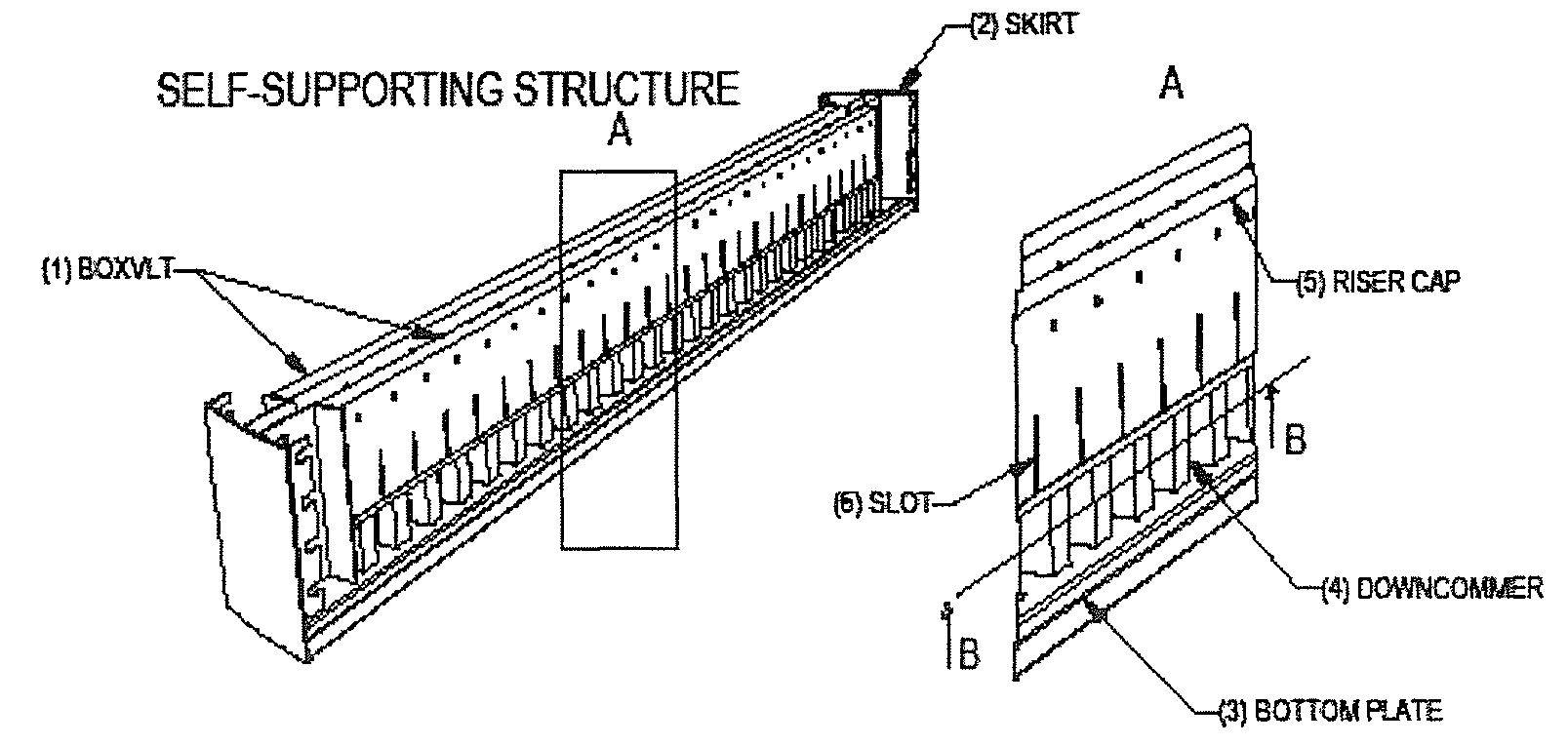
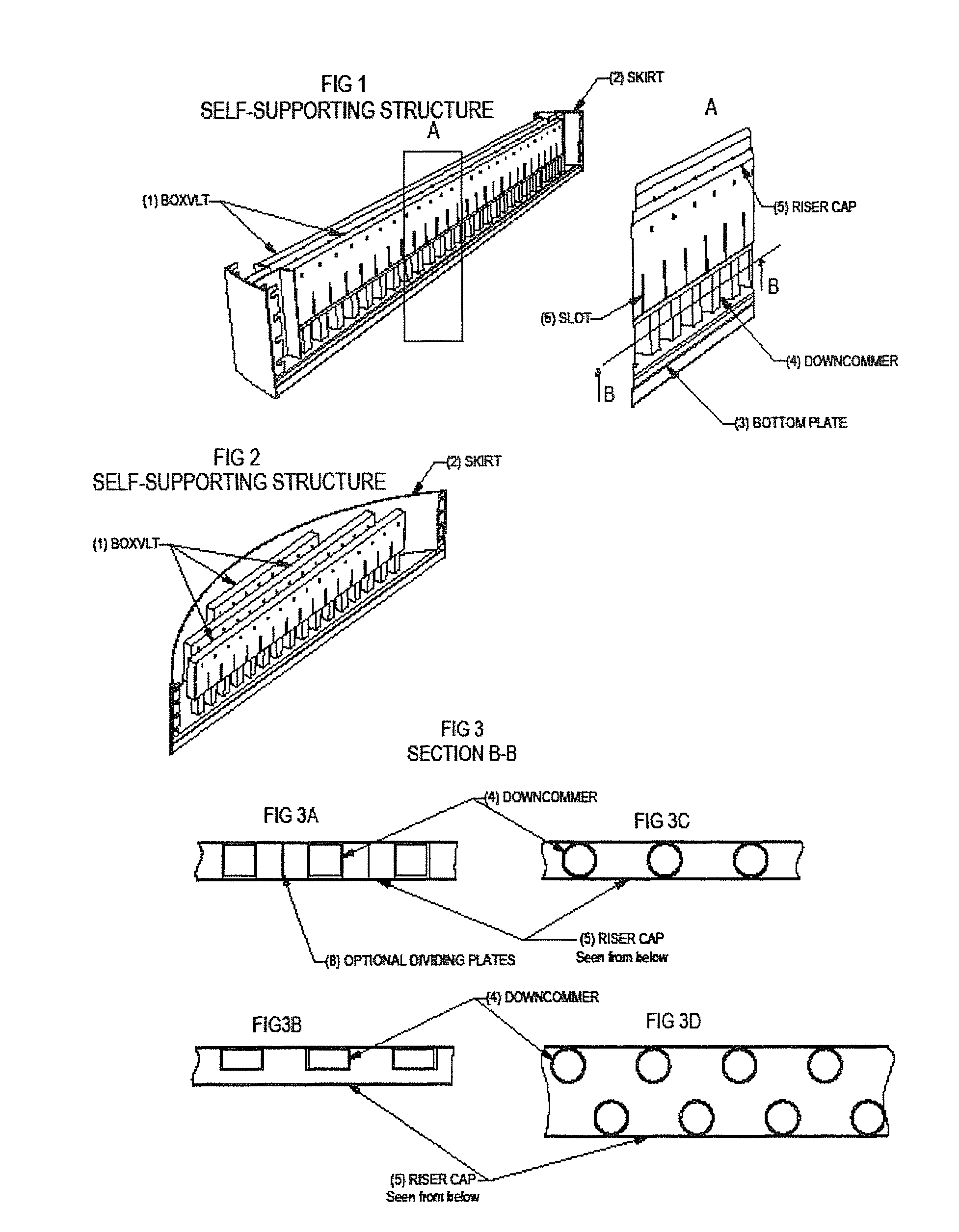
[0028]FIG. 1 shows a perspective view of the self-supporting structure, which consist of minimum one beam, which includes a riser cap, a down-corner and a bottom plate, the combination thereof is in the following description identified as box vapour lift tube or BOXVLT.

[0029]FIG. 2 is showing perspective view of a self-supporting structure with 3 BOXVLTs.

[0030]FIG. 3 (A-D) is showing cross-sectional view of the BOXVLT (seen from below) with examples of different layout of the down-corner with various shapes and various patterns.

DETAILED DESCRIPTION OF THE INVENTION

[0031]The liquid-vapour distribution design concept (referred to as self-supporting structure) is shown on FIG. 1 and FIG. 2. The device consists of one or several BOXVLT 1 extending from one side of the reactor inner wall to the other side of the reactor inner wall, a skirt 2 which is curved with a curvature corresponding to the curvature of the reactor inner wall (not shown) to a...


PUM

PropertyMeasurementUnit
sizeaaaaaaaaaa
heightaaaaaaaaaa
rough liquid distributionaaaaaaaaaa

Abstract

A liquid-vapor distribution device for use in two-phase stream concurrent down-flow vessels including:a plurality of BOXVLTs fabricated in form of self-supporting structures (beams) and tray panels when installed forms a tray which will be essentially leak free at the junctions and between the tray and the vessel wall;the horizontal self-supporting structure consisting of a bottom plate being perforated with at least one row of apertures of equal size, wherein each aperture is fitted with an elongated down-flow channel (downcomer) being in form of a tube or any other geometric shape with the same geometrical cross sectional shape as the apertures in the beam and the down-flow channel is provided with an inlet for the concurrent two-phase stream, and wherein at least two of the down-flow channels are fitted with a common riser cap being attached to and along at least one wall portion of each down-flow channel and mounted over and spaced apart the inlet of the down-flow channel.

Description

CROSS-REFERENCE TO RELATED APPLICATIONS[0001]This application claims foreign priority benefits under 35 USC 119(a)-(d) to PA2008 000029 filed in Denmark on Jan. 9, 2008.BACKGROUND OF THE INVENTION[0002]The present invention relates to a liquid-vapour distribution device for use in two-phase concurrent down-flow vessels. In particular, the invention concerns a liquid distribution device in form of a common header combining multiple vapour lift tubes (referred to as a BOXVLT) that improves distribution of liquid and vapour phases when a plurality of these BOXVLTs are assembled over a cross sectional area of a vessel in order to achieve thermal and compositional equilibrium in catalytic reactions. The device is in particular useful in hydroprocessing reactors.[0003]The known designs of liquid distribution devices fall into one of five categories. The first is a series of troughs and overflow weirs to systematically subdivide the liquid into multiple streams before it contacts a catalyt...

Claims


Application Information

Patent Timeline
Patent Type & Authority Patents(United States)
IPC IPC(8): B01F3/04B01F23/00
CPCB01D3/008B01D3/26B01J8/0492B01J8/0278B01D3/324B01J4/00B01J4/005B01J10/00
Inventor JARLKOV, KLAUS RISBJERG
Owner TOPSOE AS
Why Eureka
Try Eureka