Double-tube type stent

a double-tube type, stent technology, applied in the field of stents, can solve the problems of reducing durability, reducing flexibility, and difficult to maintain the stent in the bile duct for a long time, and achieve the effects of preventing bleeding, ensuring safety, and maximum durability and long-term usability

Active Publication Date: 2011-10-25
TAEWOONG MEDICAL CO LTD
View PDF21 Cites 26 Cited by
  • Summary
  • Abstract
  • Description
  • Claims
  • Application Information

AI Technical Summary

Benefits of technology

[0014]Accordingly, the present invention has been made keeping in mind the above problems occurring in the related art, and embodiments of the present invention provide a double-tube type stent having a dual protection structure in which a silicon coating layer is formed on the outer surface of a hollow cylindrical body woven with a superelastic shape-memory-alloy wire using a silicon solution and in which a polytetrafluoroethylene (PTFE) tube is fitted around the cylindrical body having the silicon coating layer with a gap remaining in between them, thereby providing maximum durability and long-term usability in the bile duct, and blocking the protrusion of a lesion area of the bile duct to prevent bleeding, and maximizing reliability owing to safe removal from the bile duct.
[0017]According to embodiments of the present invention, the double-tube type stent has a dual protection structure in which a silicon coating layer is formed on the outer surface of a hollow cylindrical body woven with a superelastic memory alloy wire using a silicon solution, and in which a polytetrafluoroethylene (PTFE) tube is fitted around the cylindrical body having the silicon coating layer leaving a gap therebetween, so that the silicon coating layer is protected from the strongly acidic bile inside the bile duct, thereby providing maximum durability and long-term usability in the bile duct.
[0018]Further, a lesion area of the bile duct is blocked to prevent bleeding thanks to the dual protection structure of the PFTE tube and the silicon coating layer, particularly due to a buffer function of the gap between the PFTE tube and the silicon coating layer. In addition, the double-tube type stent is safely removable from the bile duct without separately cutting off the protrusion of the lesion area, thereby maximizing reliability of use.

Problems solved by technology

However, the silicon coating layer reduces flexibility, and thus makes it difficult to maintain the stent in the bile duct for a long time.
Further, due to the strongly acidic environment inside the bile duct, the silicon coating layer is dissolved, reducing durability.
Nevertheless, the PTFE tube does not come into contact with the stent, and fails to be firmly fixed to the stent.
Accordingly, the PTFE tube brings about inconvenient use, and fails to effectively guide the bile.
However, since the thread is directly tied to the stent, it does not maintain a firmly tied state due to sliding, or the like.
In other words, since only one of the silicon coating layer and the PTFE tube has low resistance, it cannot prevent the lesion area of the bile duct from protruding, particularly, from protruding through the rhombic spaces 2 formed on the outer surface of the stent 1.

Method used


Image

  • Double-tube type stent
  • Double-tube type stent
  • Double-tube type stent

Examples


Embodiment Construction

[0024]Reference will now be made in greater detail to a preferred embodiment of the invention, an example of which is illustrated in the accompanying drawings. Wherever possible, the same reference numerals will be used throughout the drawings and the description to refer to the same or like parts.

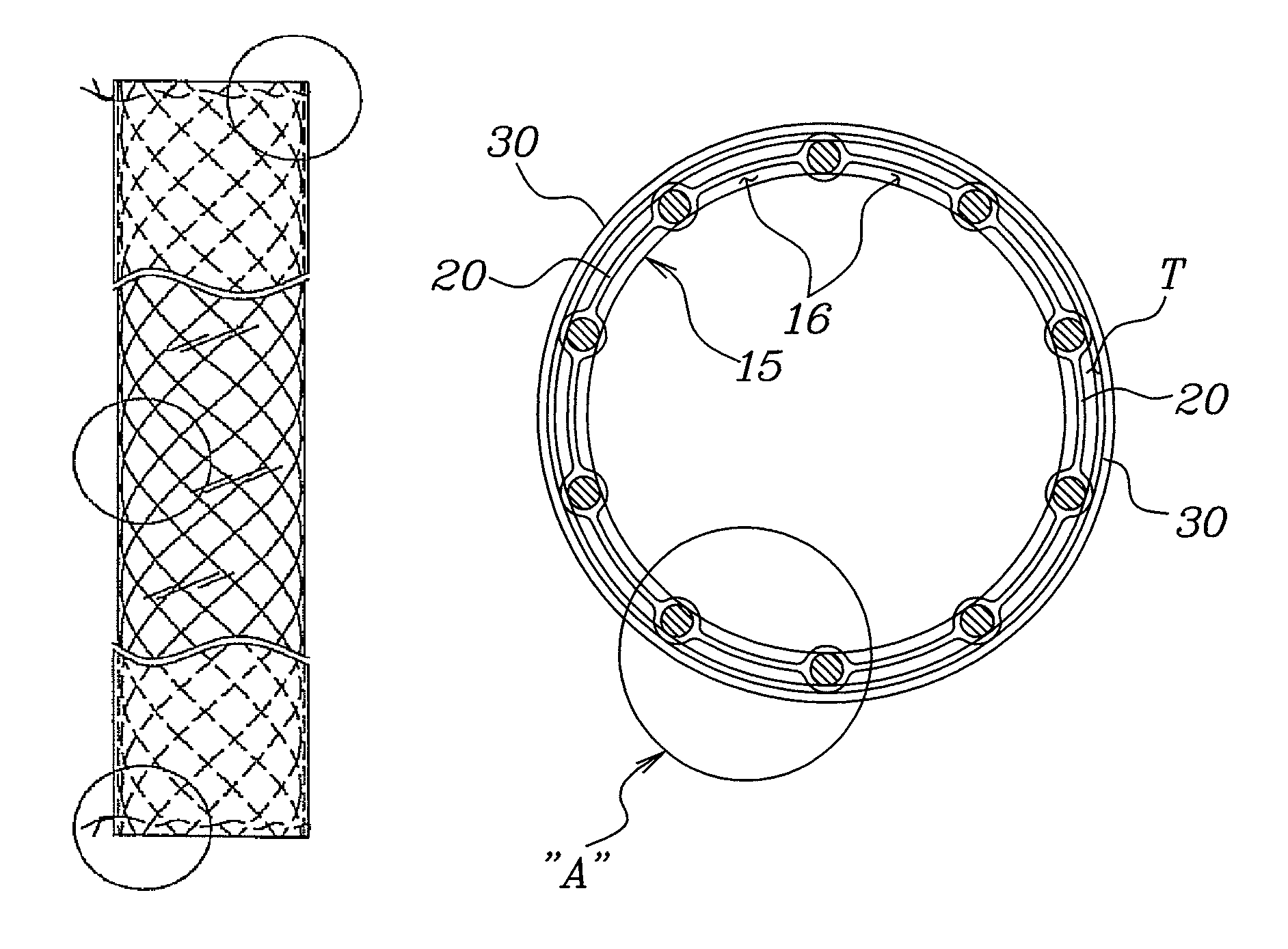
[0025]An embodiment of the present invention is characterized by a stent having a hollow cylindrical body that has a plurality of rhombic spaces formed by weaving a superelastic shape-memory-alloy wire so as to be crossed.

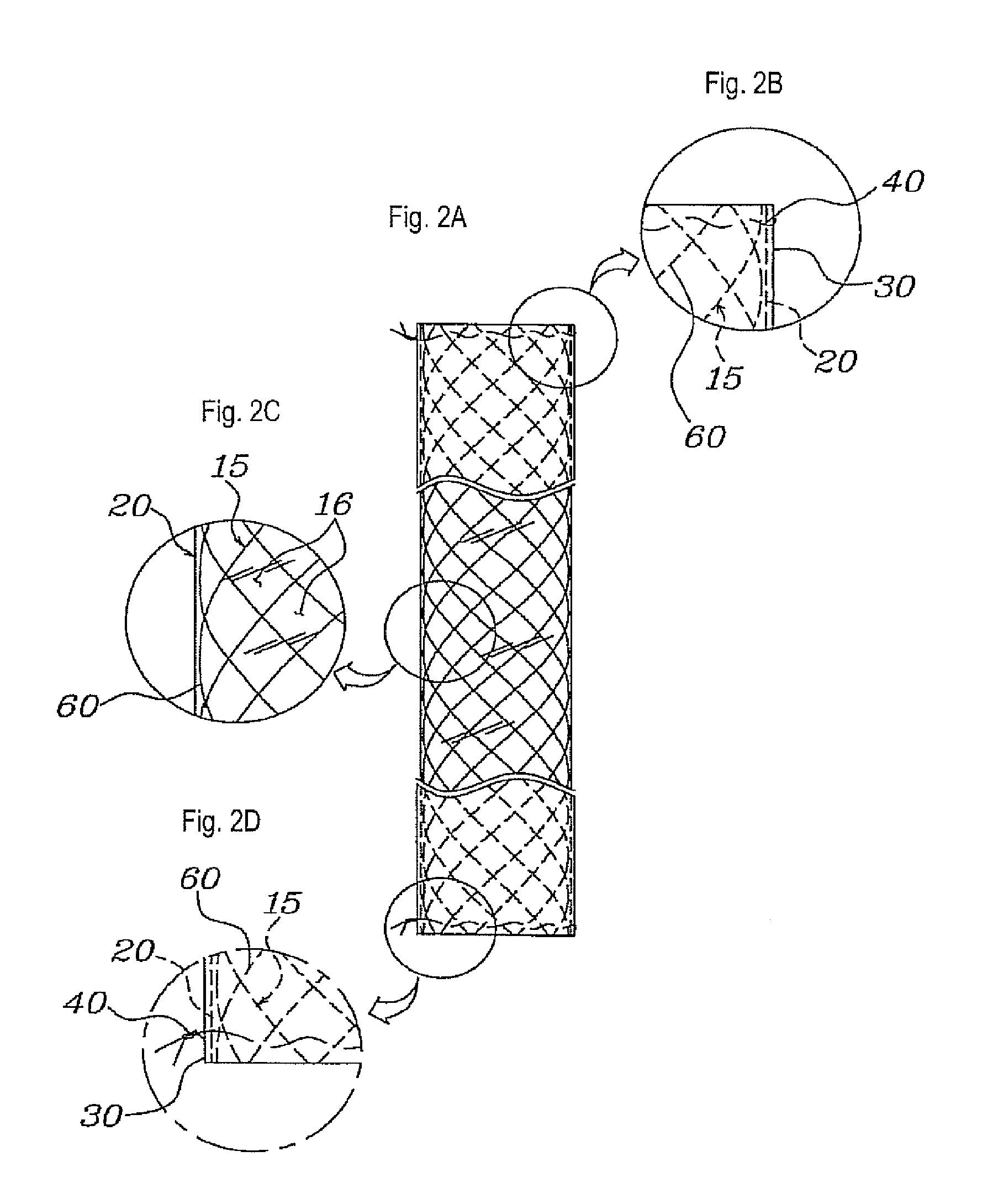
[0026]As illustrated in FIGS. 2, 3 and 4, according to an embodiment of the present invention, a double-tube type stent has a hollow cylindrical body 15, which has a plurality of rhombic spaces 16 formed by weaving a superelastic shape memory alloy wire 60 so as to be crossed and which is coated with a thin film on an outer surface thereof.

[0027]At this time, the thin film includes a silicon coating layer 20 formed by immersing the cylindrical body 15 into a silicon solut...


PUM

PropertyMeasurementUnit
superelasticaaaaaaaaaa
durabilityaaaaaaaaaa
flexibilityaaaaaaaaaa

Abstract

A double-tube type stent is inserted into a hollow tubular organ such as a bile duct so as to relieve narrowing of the bile duct on, for instance, an anastomotic area of the intrahepatic bile duct of a liver transplant patient. A hollow cylindrical body has a plurality of rhombic spaces formed by weaving a superelastic shape-memory-alloy wire so as to be crossed. A silicon coating layer is coated on an outer surface of the cylindrical body using a silicon solution. A polytetrafluoroethylene (PTFE) tube is fixedly fitted around the cylindrical body having the silicon coating layer leaving a gap therebetween.

Description

BACKGROUND OF THE INVENTION[0001]1. Field of the Invention[0002]The present invention relates, in general, to a stent that is inserted into a hollow tubular organ such as a bile duct to relieve narrowing of the hollow tubular organ, for instance, on an anastomotic area of the intrahepatic bile duct of a liver transplant patient and, more particularly, to a double-tube type stent having a dual protection structure in which a silicon coating layer is formed on the outer surface of a hollow cylindrical body woven with a superelastic shape-memory-alloy wire using a silicon solution, in which a polytetrafluoroethylene (PTFE) tube is fitted around the cylindrical body having the silicon coating layer leaving a gap therebetween, thereby providing maximum durability, long-term usability and safe removal with respect to the hollow tubular organ.[0003]2. Description of the Related Art[0004]Generally, when a hollow tubular organ, for instance a bile duct, on an anastomotic area of the intrahep...

Claims


Application Information

Patent Timeline
Patent Type & Authority Patents(United States)
IPC IPC(8): A61F2/06A61F2/07A61F2/86A61F2/94A61M29/02
CPCA61F2/07A61L31/022A61L31/10C08L83/04A61F2/90A61F2002/041A61F2002/075A61L2400/16A61F2/06A61F2/82A61F2/86
Inventor SHIN, KYONG-MINNAM, JEUNG-HEE
Owner TAEWOONG MEDICAL CO LTD
Why Eureka
Try Eureka