Electroporation cuvette with spatially variable electric field

a cuvette and electric field technology, applied in the field of electrocorrosion, can solve problems such as cell lysis

Inactive Publication Date: 2011-10-25
BIO RAD LAB INC
View PDF6 Cites 4 Cited by
  • Summary
  • Abstract
  • Description
  • Claims
  • Application Information

AI Technical Summary

Problems solved by technology

If the voltage difference is too low, the cell walls will not become sufficiently porous to allow the molecules to penetrate, and if the voltage difference is too high, the resulting dipole moment will cause cell lysis.

Method used


Image

  • Electroporation cuvette with spatially variable electric field
  • Electroporation cuvette with spatially variable electric field
  • Electroporation cuvette with spatially variable electric field

Examples


Embodiment Construction

[0012]While the features defining this invention are capable of implementation in a variety of constructions, the invention as a whole will be best understood by a detailed examination of specific embodiments. The drawings hereto represent such embodiments.

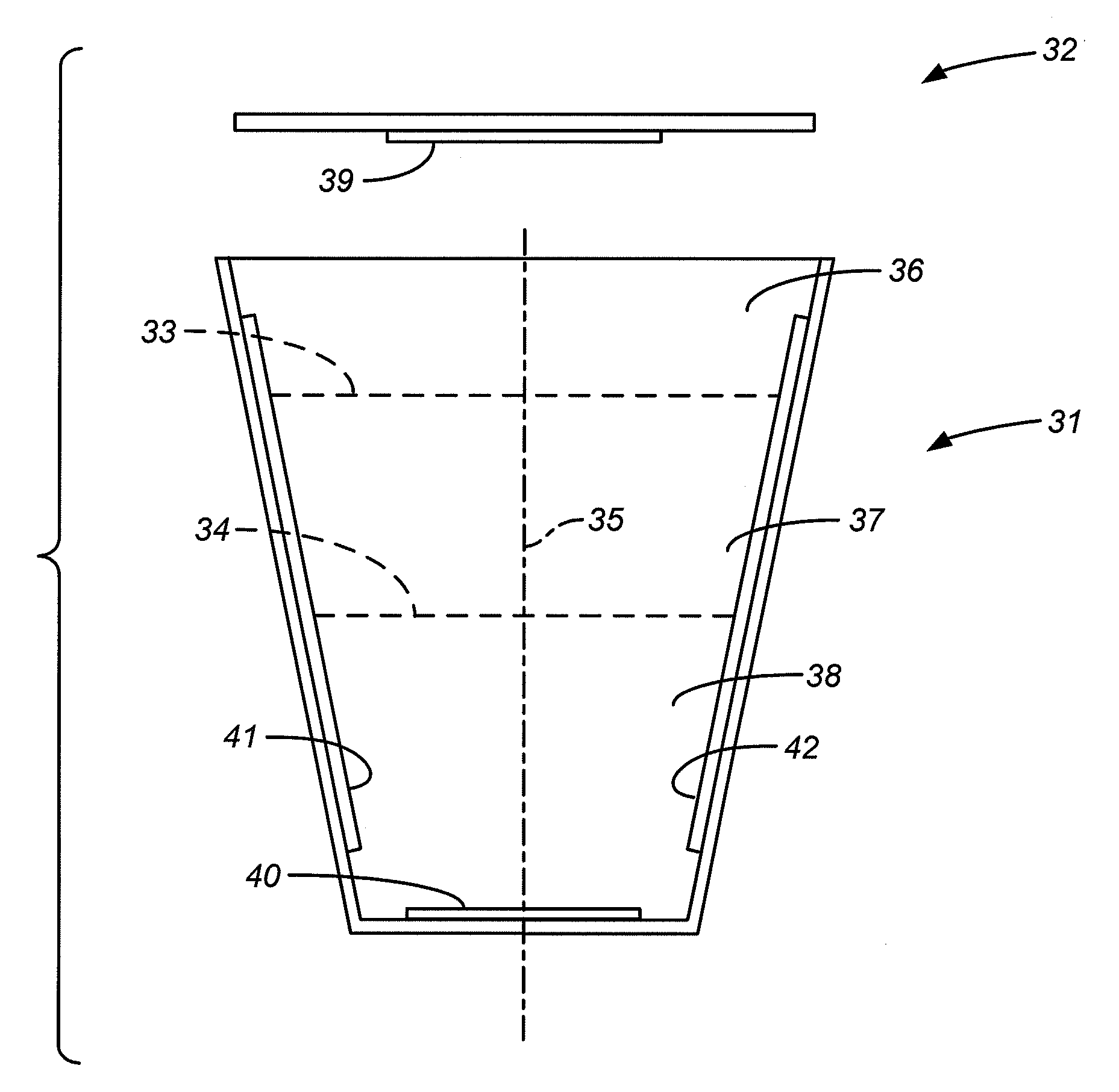
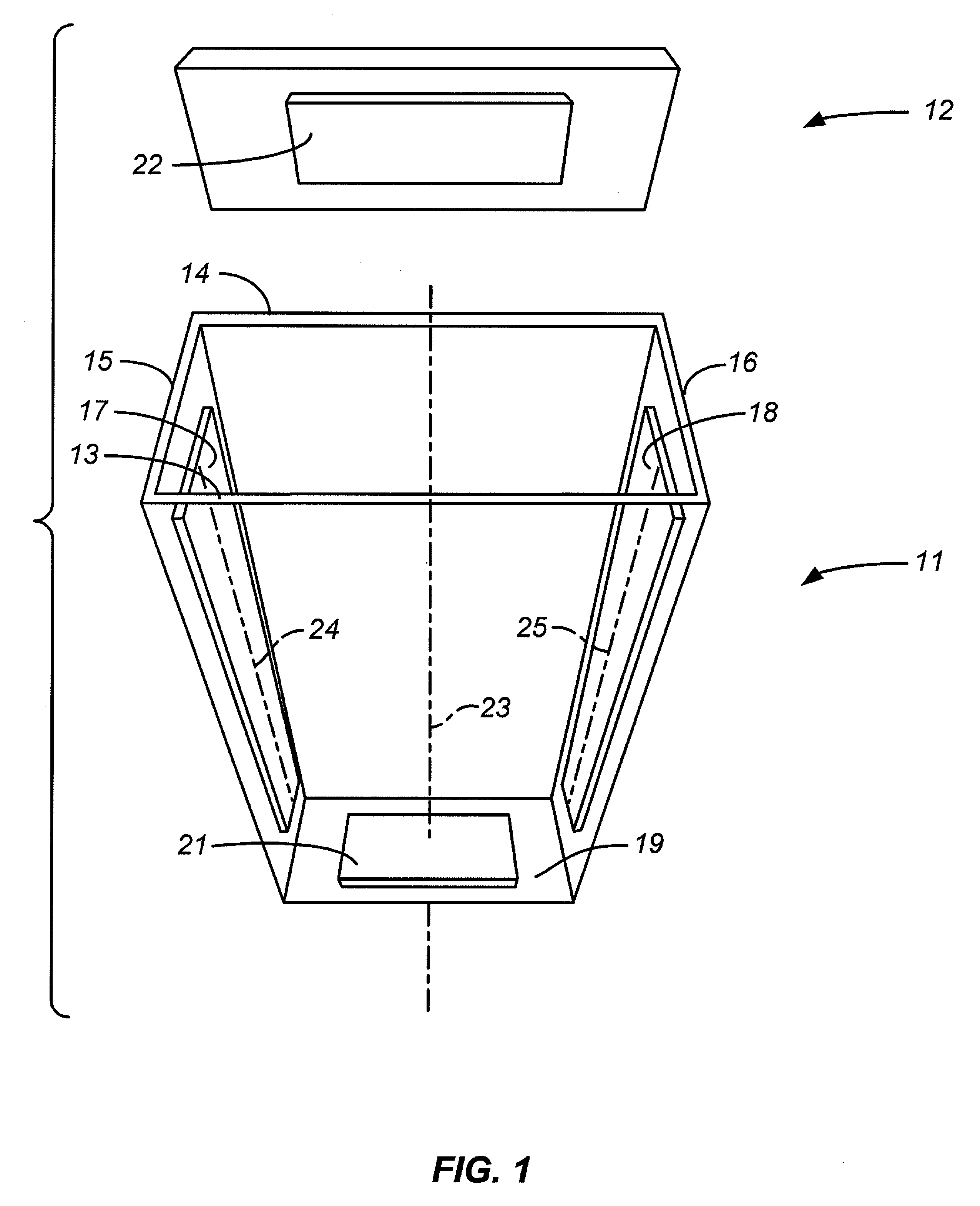
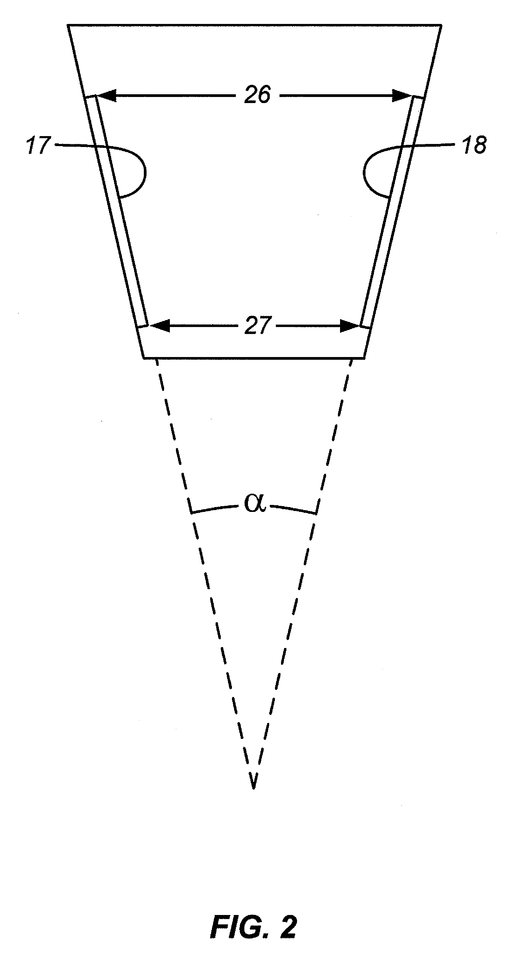
[0013]The cuvette 11 shown in FIG. 1 has an open top and a lid 12 which can be attached or separate. The cuvette 11 is rectangular in its horizontal cross section with planar walls on four sides. The front wall 13 and back wall 14 are parallel while the end walls 15, 16 are angled to form a tapering profile with the widest separation at the top and the narrowest at the base. Affixed to the two end walls and exposed to the interior of the cuvette are a pair of opposing electrodes 17, 18 which, due to the sloping walls to which they are attached, are non-parallel. These electrodes are the shocking electrodes, and due to their non-parallel arrangement, the separation between these electrodes near the top of the cuvette is greater tha...


PUM

PropertyMeasurementUnit
angleaaaaaaaaaa
angleaaaaaaaaaa
sizeaaaaaaaaaa

Abstract

An electroporation cuvette is constructed with electroporation electrodes arranged in non-parallel relation to form a gap whose width varies with the location within the cuvette, plus a pair of positioning electrodes that are arranged to cause electrophoretic migration of biological cells within the cuvette according to cell size. Once the cells, suspended in a solution of the impregnant, are distributed in the cuvette by the positioning electrodes, electric field pulses are generated by the non-parallel electroporation electrodes. Because of their distribution in the cuvette, the various cells will experience voltage differentials across their widths that approach uniformity regardless of cell diameter, since the larger cells will be positioned at locations where the gap between the electrodes is greater and the smaller cells at locations where the gap is relatively small while the voltage drop across the entire gap is uniform along the length of the cell. The voltage differential across the width of the cell is thus roughly paired with the cell diameter, and this reduces the disparity in voltage differential that cells of different sizes would otherwise experience with parallel electrodes.

Description

CROSS-REFERENCE TO RELATED APPLICATION[0001]This application claims the benefit of U.S. Provisional Patent Application No. 61 / 030,074, filed Feb. 20, 2008, the contents of which are incorporated herein by reference in their entirety.BACKGROUND OF THE INVENTION[0002]1. Field of the Invention[0003]This invention lies in the field of electroporation, the process by which exogenous molecular species are inserted into membranous structures by suspending the structures in a liquid solution of the exogenous species and applying an electric field to the resulting suspension. In particular, this invention addresses electroporation cuvettes.[0004]2. Description of the Prior Art[0005]Electroporation, or electric pulse-driven transfection, is widely used for impregnating membranous structures, such as living biological cells, liposomes, and vesicles, with exogenous molecules. The structures are typically suspended in an aqueous solution of the exogenous species in a high-conductivity buffer. No...

Claims


Application Information

Patent Timeline
Patent Type & Authority Patents(United States)
IPC IPC(8): C12N13/00
CPCC12M25/02C12M35/02C12N13/00
Inventor RAGSDALE, CHARLES W.
Owner BIO RAD LAB INC
Why Eureka
Try Eureka