
Back light apparatus and control method thereof

a back light and control method technology, applied in process and machine control, instruments, color signal processing circuits, etc., can solve the problems of different voltages, different power consumption, and reduced lighting efficiency

Inactive Publication Date: 2011-10-25
SAMSUNG ELECTRONICS CO LTD
View PDF18 Cites 55 Cited by
  • Summary
  • Abstract
  • Description
  • Claims
  • Application Information

AI Technical Summary

Benefits of technology

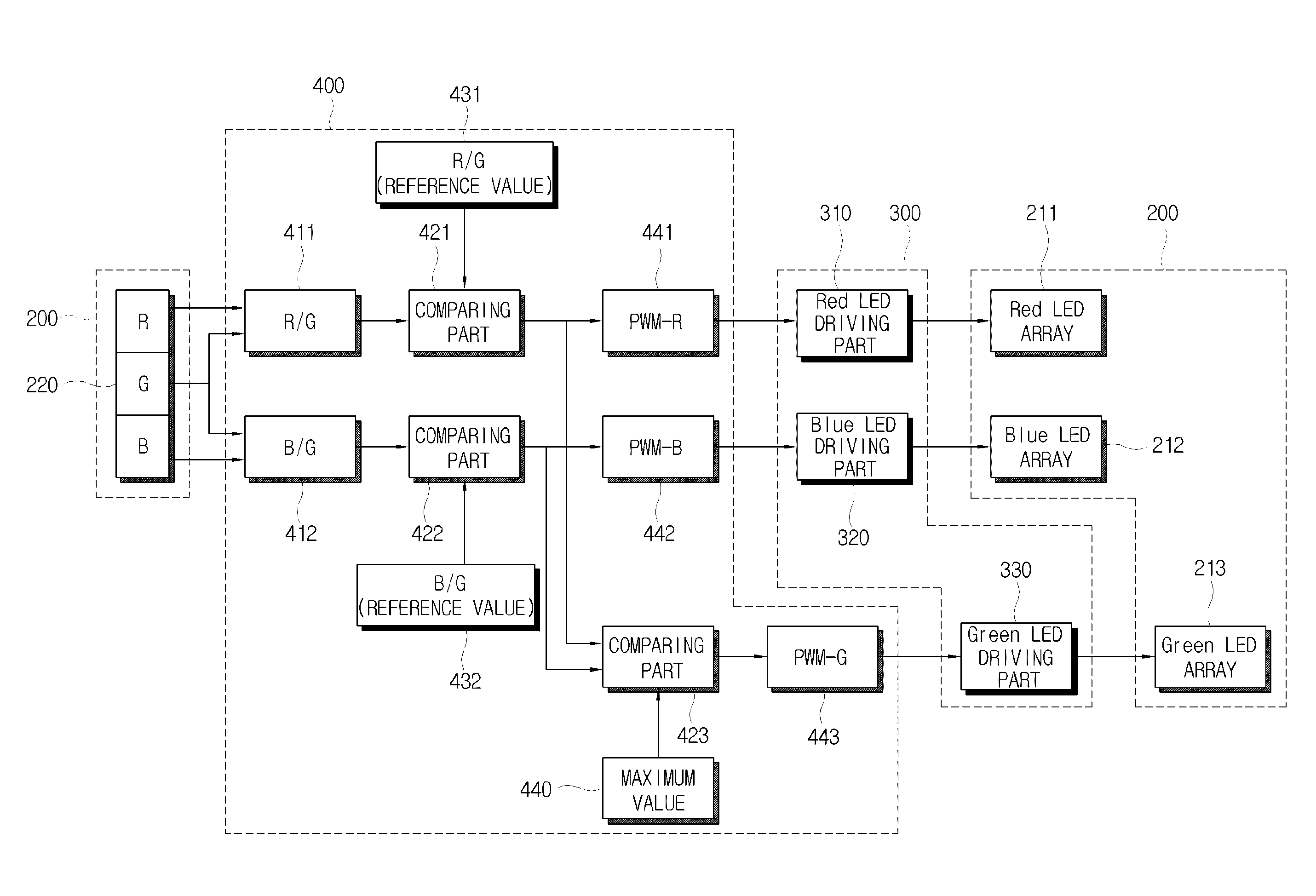
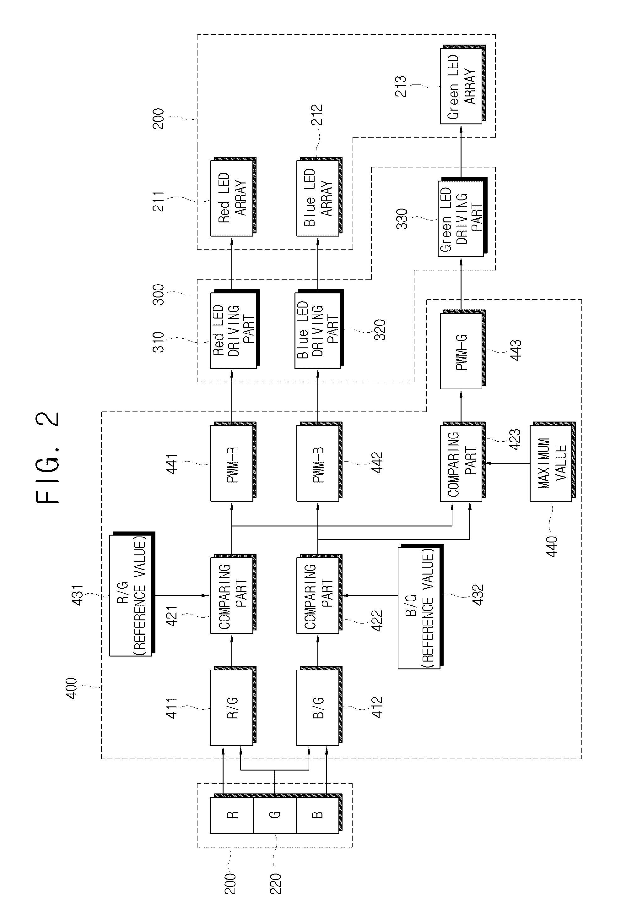
[0010]The present invention provides a back light apparatus capable of controlling a color without changing an output reference of a light sensor and in optimum brightness despite deterioration of a light source if the back light apparatus uses LEDs corresponding to a plurality of colors, and a control method thereof.
[0013]The controller may control the driving part to adjust a current input to the LEDs so that the color ratio between two colors becomes a value.
[0016]The controller may control the driving part to adjust PWM of the current input to the LEDs so that the color ratio between two colors becomes the value.

Problems solved by technology

Also, the LEDs for different colors are receive different voltages and consume different power because they are different from one another in semiconductor composition.
However, the lighting efficiency decreases if time is passed.
In other words, if the back light apparatus controls the brightness of the LED based on the output of the LED, the brightness is not correctly adjusted because the output is changed depending on deterioration of the LED.
Also, if the brightness of the light source should be controlled per frame unit, it is not desirable to control the brightness while changing an output reference of the sensor per the frame unit, and it is practically difficult to be controlled by this method.

Method used


Image

  • Back light apparatus and control method thereof
  • Back light apparatus and control method thereof
  • Back light apparatus and control method thereof

Examples


Embodiment Construction

[0030]Reference will now be made in detail to exemplary embodiments of the present invention, examples of which are illustrated in the accompanying drawings, wherein like reference numerals refer to like elements throughout. The exemplary embodiments are described below so as to explain the present invention by referring to the figures.

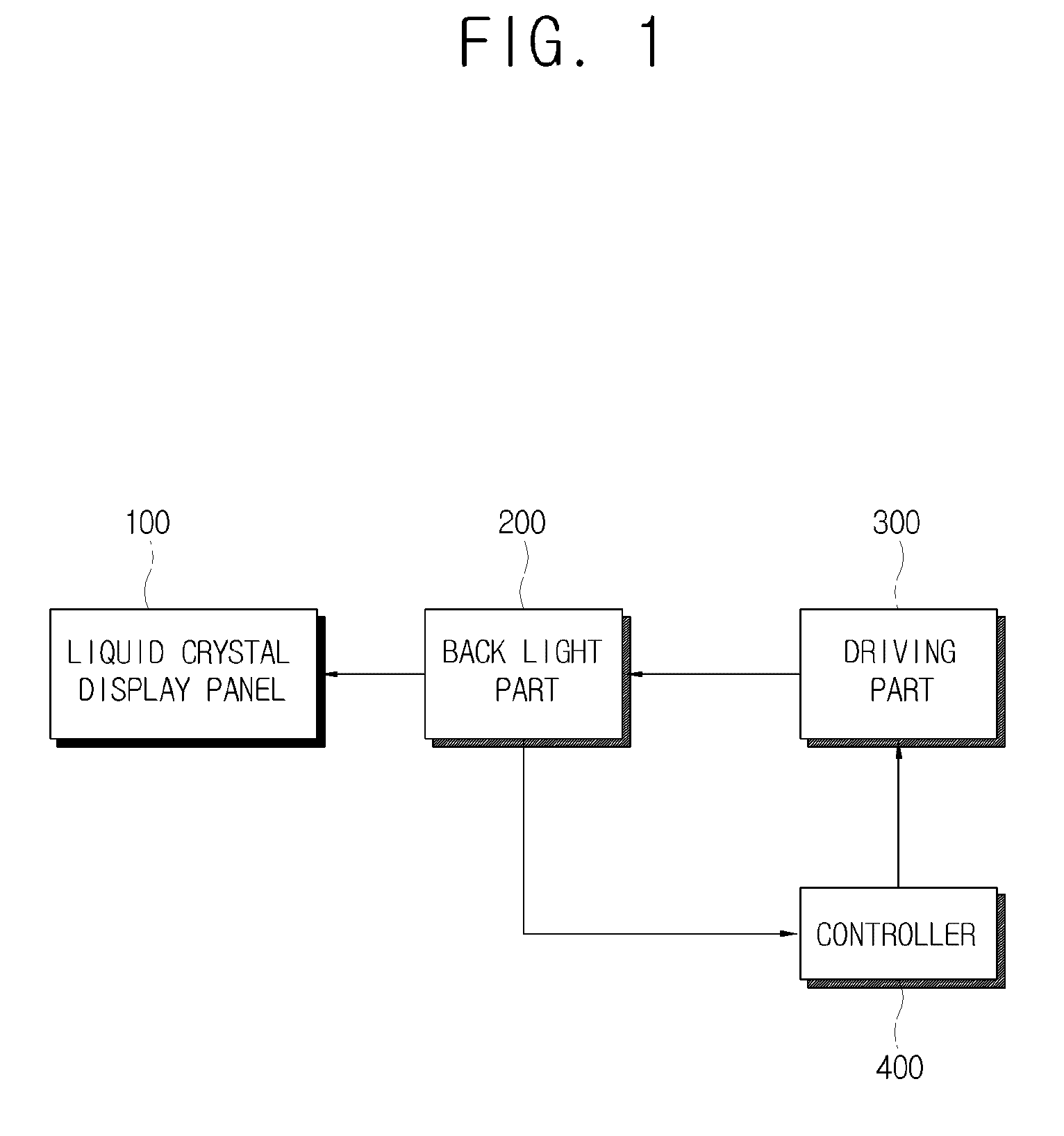
[0031]As shown in FIG. 1, a liquid crystal display apparatus includes a liquid crystal display panel 100, a back light part 200, a driving part 300 and a controller 400. The liquid crystal display panel 100 includes a first substrate on which a switching element (not shown) and a pixel electrode (not shown) are formed; a second substrate on which a red color filter, a green color filter and a blue color filter are formed; and a liquid crystal between the first substrate and the second substrate. A signal from a panel driving part (not shown) is transmitted to the switching element through a Printed Circuit Board (PCB) provided on a source side of the ...


PUM


Abstract

A back light apparatus includes a back light part which emits light to a liquid crystal display panel, and includes a plurality of LEDs respectively corresponding to a plurality of colors, a detecting part which detects the light emitted from the plurality of the LEDs, a driving part which drives the LEDs to emit, and a controller which controls the driving part to make color ratios substantially equal to a reference value if the reference value is not equal to the color ratio between at least two colors among the plurality of colors of the light detected in the detecting part.

Description

CROSS-REFERENCE TO RELATED APPLICATIONS[0001]This application claims priority from Korean Patent Application No. 2006-0121780, filed on Dec. 4, 2006 in the Korean Intellectual Property Office, the disclosure of which is incorporated herein by reference.BACKGROUND OF INVENTION[0002]1. Field of Invention[0003]Apparatuses and methods consistent with the present invention relate to a back light apparatus and a control method thereof, and more particularly, to a back light apparatus which uses light emitting diodes (LEDs) of various colors as a light source, and a control method thereof[0004]2. Description of the Related Art[0005]In the related art back light apparatus using an LED as a light source, a red LED (R LED), a green LED (G LED) and a blue LED (B LED) respectively have different lighting efficiencies. Accordingly, currents to be supplied to the LEDs for respective colors are different from one another. Also, the LEDs for different colors are receive different voltages and consu...

Claims


Application Information

Patent Timeline
Patent Type & Authority Patents(United States)
IPC IPC(8): G09G3/38H05B44/00
CPCG09G3/3413H04N9/73H05B33/086H05B33/0869G09G2320/043G09G2320/0666Y02B20/341G09G2360/145H05B45/22Y02B20/30G02F1/133H05B45/20
Inventor CHOI, HOON
Owner SAMSUNG ELECTRONICS CO LTD
Learn More