Recording material determination apparatus and image forming apparatus
a technology of material determination and recording material, which is applied in the direction of electrographic process apparatus, thin material processing, instruments, etc., can solve the problems of insufficient determination accuracy in the conventional method, difficult to finely determine the grammage of a recording material, and capture of unfocused image of the surface of the recording material
- Summary
- Abstract
- Description
- Claims
- Application Information
AI Technical Summary
Benefits of technology
Problems solved by technology
Method used
Image
Examples
first exemplary embodiment
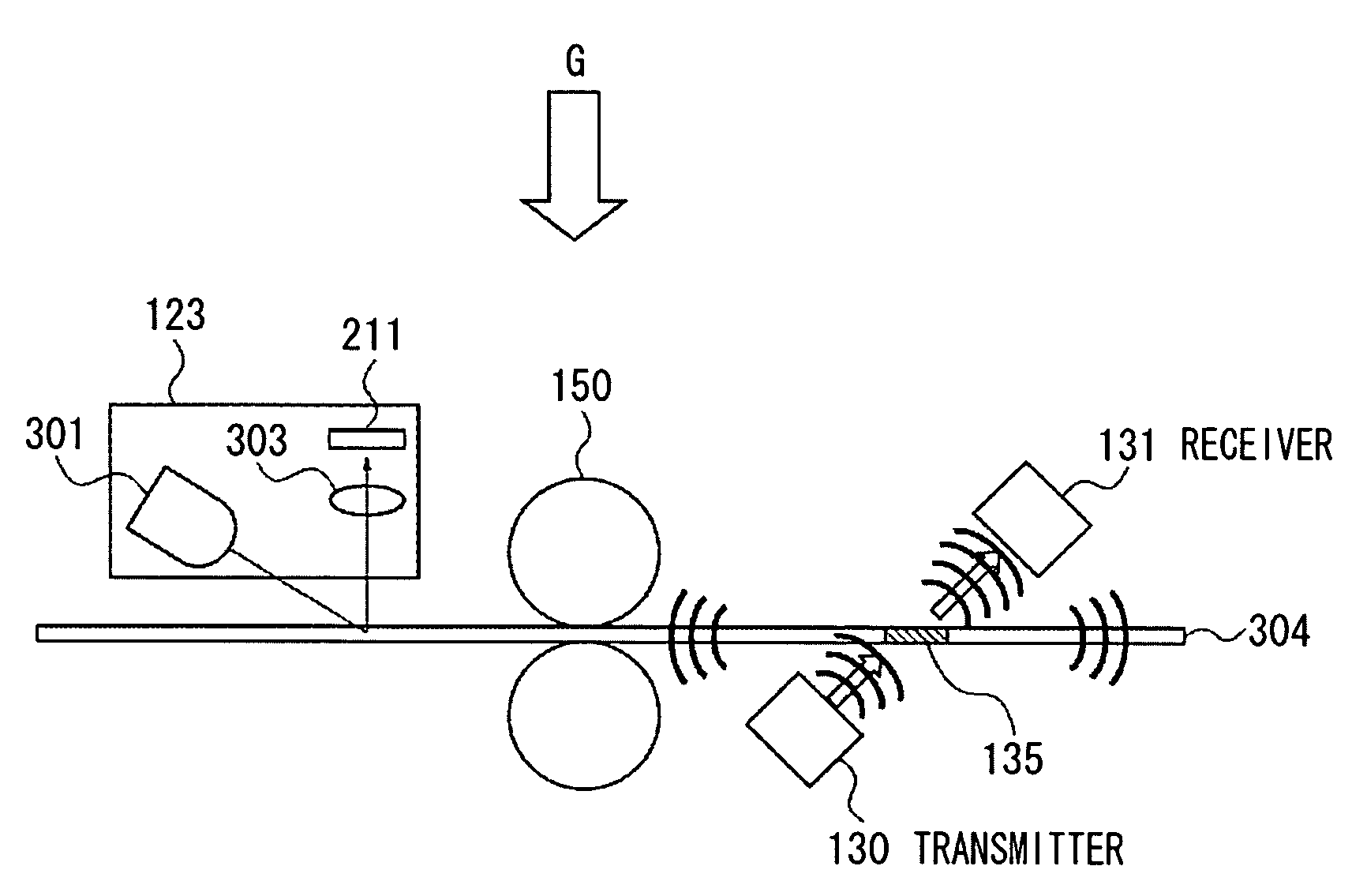
Next, a recording material determination apparatus according to an exemplary embodiment of the present invention is described below. FIG. 3 illustrates a configuration of a reading sensor for determining a surface condition of a recording material. FIG. 4 illustrates a configuration of an ultrasonic sensor for determining a grammage of a recording material.
As illustrated in FIG. 3, the reading sensor 123 for determining the surface condition of a recording material includes a light emitting diode (LED) 301 for irradiating light, a CMOS area sensor 211 for capturing an image, and an imaging lens 303. Incidentally, an image can be captured using a CCD sensor instead of the CMOS area sensor 211.
Light emitted from the LED 301 serving as a light source is irradiated to a surface of the recording material 304. Reflection light reflected from the recording material 304 is focused via the lens 303 and is formed into an image on the CMOS area sensor 211. Consequently, an image of the surface...
second exemplary embodiment
A configuration of components of a second exemplary embodiment other than the arrangement of the reading sensor 123, the ultrasonic transmitter 130 and the ultrasonic receiver 131, which serve as a ultrasonic sensor, the conveyance roller 150, and the recording material 304 is similar to that of components of the first exemplary embodiment. Therefore, the detailed description of such components of the second exemplary embodiment is omitted.
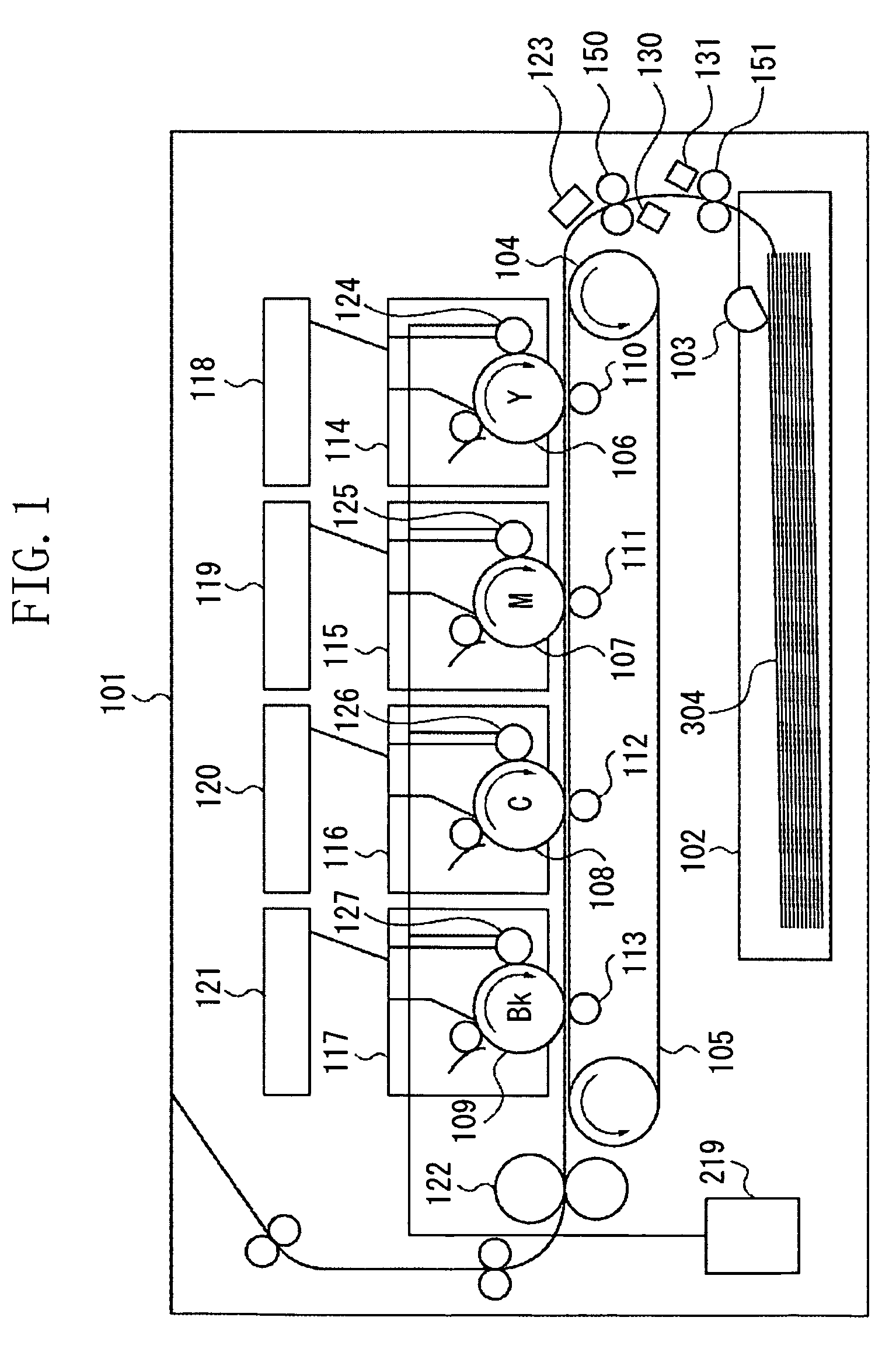
In the first exemplary embodiment, the reading sensor 123 is located opposite the ultrasonic sensor across the conveyance roller 150 in the direction of conveying the recording material 304.
In the second exemplary embodiment, the conveyance roller 150 is configured to include a plurality of conveyance members 150A and 150B provided on a shaft 151, as illustrated in FIG. 14. The reading sensor 123 is located between the conveyance members 150A and 150B. That is, as illustrated in FIG. 14, the reading sensor 123 detects substantially a central part ...
third exemplary embodiment
A configuration of components of a third exemplary embodiment other than the provision of a recording material detection unit therein is similar to those of components of the first and second exemplary embodiments. Therefore, the detailed description of components of the third exemplary embodiment, which are common to the first, second, and third exemplary embodiments, is omitted.
In the first and second exemplary embodiments, the CPU 210 stops the conveyance of the recording material 304 by stopping the rotation of the conveyance roller 150 at a time at which the recording material 304 is expected to reach the reading sensor 123 and at which a predetermined time period has elapsed since a paper feed timing.
On the other hand, in the third exemplary embodiment, a recording material detection unit 305 is added to a position at the downstream side of the conveyance roller 150 in the direction of conveying the recording material 304, as illustrated in FIG. 15. For example, a system confi...
PUM
 Abstract
Description
Claims
Application Information
 - R&D
- Intellectual Property
- Life Sciences
- Materials
- Tech Scout
- Unparalleled Data Quality
- Higher Quality Content
- 60% Fewer Hallucinations
Browse by: Latest US Patents, China's latest patents, Technical Efficacy Thesaurus, Application Domain, Technology Topic, Popular Technical Reports.
© 2025 PatSnap. All rights reserved.Legal|Privacy policy|Modern Slavery Act Transparency Statement|Sitemap|About US| Contact US: help@patsnap.com


