
Toner for developing electrostatic image

a technology for developing electrostatic images and toners, which is applied in the direction of electrographic processes, electrographic processes using charge patterns, instruments, etc., can solve the problems of difficult friction charge, poor powder flow ability of toner particles with a small particle diameter, and high cost of conventional grinding methods

Inactive Publication Date: 2005-07-28
RICOH KK
View PDF10 Cites 39 Cited by
  • Summary
  • Abstract
  • Description
  • Claims
  • Application Information

AI Technical Summary

Benefits of technology

[0053] In a 29th aspect, a toner for developing an electrostatic image according to any of the aspects 26 to 28, further including a charge control agent, wherein the abundance of the charge control agent on the surface of the toner is higher than that in the inside of the toner.
[0054] In a 30th aspect, a toner for developing an electrostatic image according to the 29th aspect, wherein the charge control agent is externally added to the surface of the toner base particles.
[0055] In a 31st aspect, a toner for developing an electrostatic image according to the 30th aspect, wherein the external addition of a charge control agent particle to the surface of the toner

Problems solved by technology

The manufacture of above-described toners with a particle diameter of 7 μm or less requires much cost when using a conventional grinding method.
When toner particles have a small diameter and a very smooth surface, they are very difficult to be frictionally charged.
Toner particles with a small particle diameter have very poor powder flow ability.
In either of the one-component developing apparatus or the two-component developing apparatus, toner particles are frictionally charged while rolling on and contacting with the surface of either a developing roller or carrier particles, thus small-diameter toner particles that have poor powder flowability and a rolling property are hard to be frictionally charged, and thus are regarded as inferior in uniformity.
In addition, when the toner particles have a smooth surface, the frictional charging property thereof is further deteriorated.
Although the mechanism has not been accurately elucidated, it is considered that a slip phenomenon occurs between a toner and a frictional charging member, which prevents the toner from obtaining a sufficient quantity of frictional charge.
More particularly, it is considered that the smooth surface of the toner inhibits the toner from obtaining appropriate resistance against a toner layer thickness controlling blade used in one-component developing apparatus, or against a carrier used in two-component developing apparatus, thus the toner cannot obtain a sufficient quantity of frictional charge.
Thus, if a toner could not obtain a sufficient quantity of frictional charge and has a broad distribution of frictional charge quantity, it develops even on a non-image area on a photoconductor, causing scumming.
The grinding method can manufacture a toner with rather excellent properties, but the selection of the materials of the toner is limited.
In addition, under the grinding method, it is difficult to homogeneously disperse the colorant, the charge control agent or the like in a thermoplastic resin.
Uneven dispersion of the compounding agents adversely affects the properties of the toner such as flow ability, development property, durability and image quality.
However, toner particles prepared by the suspension polymerization method are spherical, and thus are inferior in cleanability.
In the development and transfer of an object with a low ratio of image area, less residual toner is left and cleaning failure will cause no problem, but on an object with a high ratio of image area such as a photo image, the toner which formed an image that has not been transferred by a certain cause such as paper feeding failure may also occur as transfer residual toner, and accumulation thereof will cause scumming.
However, the toner particles prepared by the emulsion polymerization method have an abundance of residual surfactants not only on the surface but also in the inside of the particle, even after a washing process.
This impairs the environmental stability of the toner charge, and broadens the charge distribution to cause a bad scumming on the resulting image.
The residual surfactant also contaminates a photoconductor, a charging roller, a developing roller and the like, inhibiting them from delivering their intrinsic charging effect.
However the charging property is insufficient and apts to be separated from the surface, and the manufacture method has not provided a desired charging property.
In particular, the method is not intended to consider the initial charging rate of the toner.
An inner wall that is not smooth and has projections on it are likely to cause turbulence in a high-velocity airflow, thus it tends to cause excessive grinding of the particles, local fusion on the surface of the particles, embedding of the charge control agent below the surface of the particles, and uneven powder treatment.
More specifically, treatment through such a narrow gap may generate an abundance of heat due to an impact strength in an airflow, which causes the deformation of the toner particles and the progress of the grinding of the toner particles, resulting in the deviation of the average particle diameter and of the particle distribution from the desired ones.
Besides, the charge control agent embedded below the surface of the particles might fail to fulfill its function.
Regarding actual productivity, the quantity of the treated powder is extremely smaller in comparison with the space for treatment because of the heat generation and excessive grinding of the powder, thus the method is unsuitable to efficient production.
However, under these methods, the lower limit of fixing temperature increases, which causes the insufficient low-temperature fixing property or energy-saving fixing property.
However, the preparation of toner particles of indefinite form by associating the resin fine particles obtained by the emulsion polymerization method presents problems as described below.
When the fine particles of a release agent are associated with each other to improve the anti-offset property, the fine particles of the release agent are captured in the toner particles, resulting in the insufficient improvement in the anti-offset property.
Since the toner particles are formed of randomly fused resin fine particles, release agent, colorant and other additives; the composition (the content ratio of the components), the molecular weight of the component resin and other properties vary among the obtained toner particles, which results in the difference in the surface properties among the toner particles, making it impossible to form a stable image for a long term.
In a low-temperature fixing system that requires the low-temperature fixing property, fixing inhibition is caused by the resin fine particles unevenly distributed on the toner surface, this makes it impossible to secure the width of the fixing temperature.

Method used


Image

  • Toner for developing electrostatic image
  • Toner for developing electrostatic image
  • Toner for developing electrostatic image

Examples


example 1

[0205] 451 g of 0.1 M-Na3PO4 aqueous solution was added to 709 g of ion exchange water, and the mixture was heated to 60° C. and stirred with a TK homomixer at 12,000 r.p.m. To the mixture, 68 g of 1.0 M-CaCl2 aqueous solution was gradually added, and an aqueous medium containing Ca3(PO4)2 was obtained. 170 g of styrene, 30 g of 2-ethylhexyl acrylate, 10 g of Regal 400R, 60 g of paraffin wax (s.p. 70° C.), 5 g of di-tert-butyl salicylate metal compound, 10 g of styrene-methacrylic acid copolymer (Mw 50,000, acid value 20 mg KOH / g) were charged into a TK homomixer, heated to 60° C., and homogeneously dissolved and dispersed at 12,000 r.p.m. 10 g of 2,2′-azobis(2,4-dimethylvaleronitrile) as a polymerization initiator was dissolved in the dispersion to prepare a polymer-monomer system.

[0206] The polymer-monomer system was put in the aqueous medium, and stirred with a TK homomixer at 10,000 r.p.m. for 20 minutes at 60° C. in a N2 atmosphere to pulverize the polymer-monomer system. Afte...

example 2

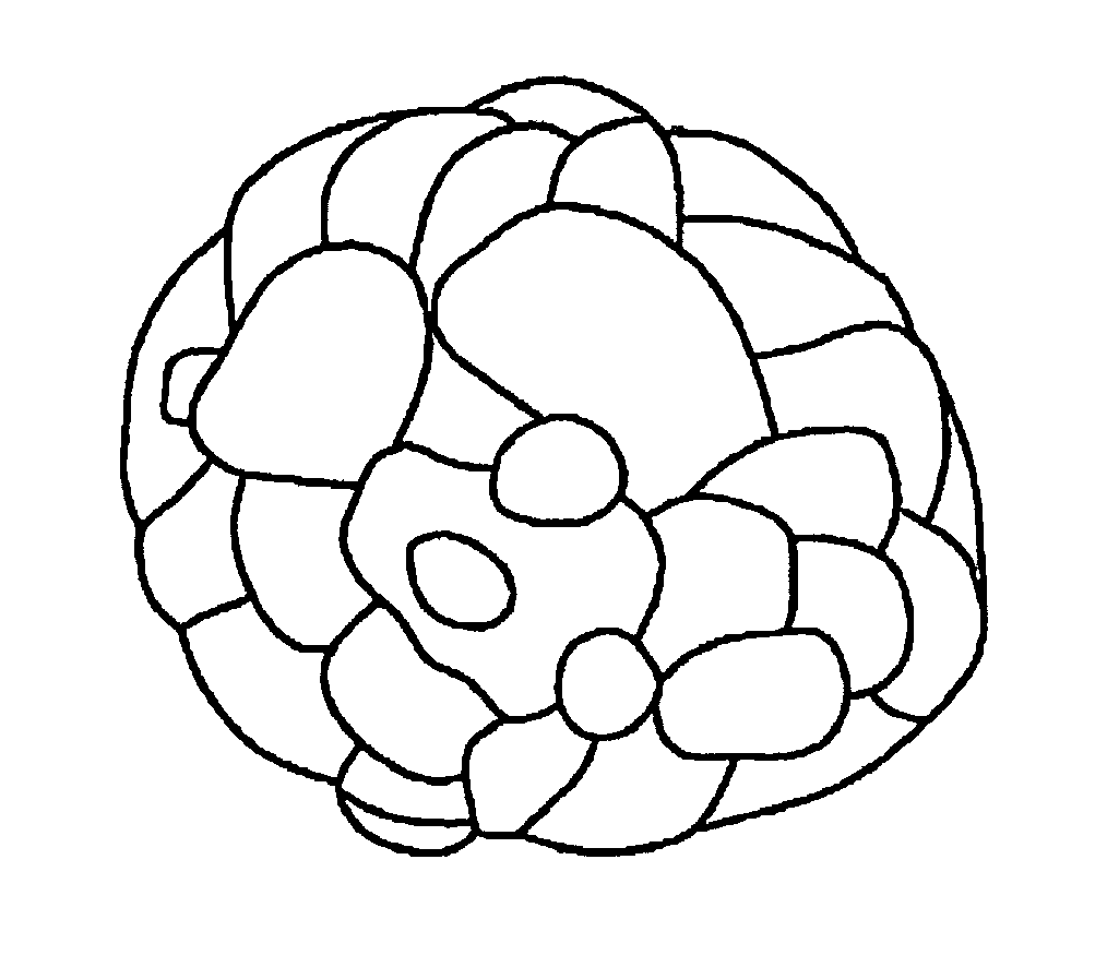
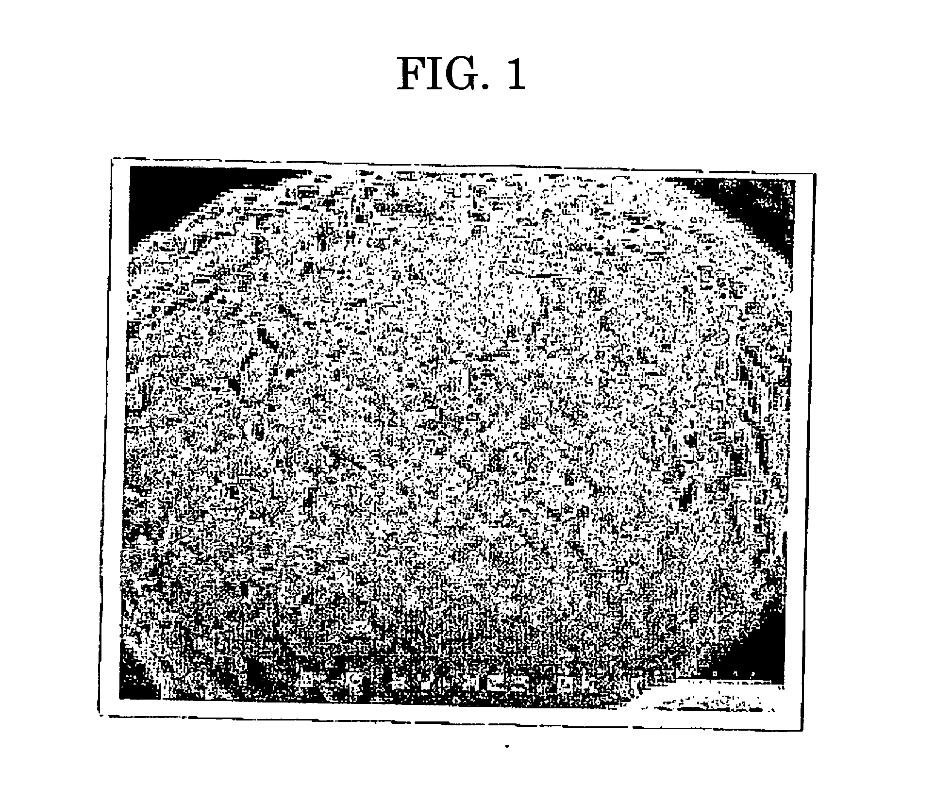
[0208] To 100 parts of the solid of the dispersion of colored particles 1 as described in Example 1, one part (in terms of solid) of Aqualic GL (manufactured by Nippon Shokubai Co., Ltd.) was added as a surface treating agent, stirred at room temperature for one hour, and dried with a spray drier GS31 (manufactured by Yamato Science Co., Ltd.) to obtain [toner 2]. According to an observation with a SEM, the surface of toner 2 was not wholly but partially in scab form.

example 3

(1) (Synthesis of Organic Fine Particle Emulsion)

[0211] 683 parts of water, 11 parts of a sodium salt of a sulfate ester of an adduct of ethylene oxide methacrylate (Eleminol RS-30: manufactured by Sanyo Chemical Industries, Ltd.), 138 parts of styrene, 138 parts of methacrylic acid, and 1 part of ammonium persulfate were stirred for 15 minutes at 400 r.p.m. in a reaction vessel equipped with a stirring rod and a thermometer to obtain a white emulsion. The emulsion was heated until the temperature in the system reached 75° C., and allowed to react for five hours. The reactant was further added with 30 parts of 1% ammonium persulfate aqueous solution, and aged at 75° C. for five hours to obtain an aqueous dispersion of a vinyl resin (copolymer of styrene-methacrylic acid-sodium salt of sulfate ester of an adduct of ethylene oxide methacrylate) [fine particle dispersion 1]. The volume average particle diameter of [fine particle dispersion 1] measured by a LA-920 was 0.14 μm. A part ...


PUM

PropertyMeasurementUnit
Lengthaaaaaaaaaa
Lengthaaaaaaaaaa
Fractionaaaaaaaaaa

Abstract

A toner for developing an electrostatic image which has a small particle size essential for attaining a high-quality image, and can output a high-quality image excellent in frictional charging property and free from scumming. The toner for developing an electrostatic image has the volume average particle diameter of 2.0 μm to 7.1 μm and the surface condition of the toner is in scab form.

Description

CROSS-REFERENCE TO RELATED APPLICATIONS [0001] This is a continuation of Application No. PCT / JP2003 / 008315, filed on Jun. 30, 2003.BACKGROUND OF THE INVENTION [0002] 1. Field of the Invention [0003] The present invention relates to a toner for developing an electrostatic image for developing an electrostatic charge image formed on the surface of a photoconductor in electrophotography, electrostatic recording or the like, a developer containing the toner, an image forming method using the toner, a toner container containing the toner, and an image forming apparatus equipped with the toner. [0004] 2. Description of the Related Art [0005] In recent years, toners with smaller particle diameters have been actively developed at the strong request of the market for higher image quality, thus toners with an average particle diameter of 7 μm or less are currently on the market. The manufacture of above-described toners with a particle diameter of 7 μm or less requires much cost when using a ...

Claims


Application Information

Patent Timeline
IPC IPC(8): G03G9/087G03G9/08G03G9/097G03G15/08G03G15/20
CPCG03G9/0819G03G9/0825G03G9/0827G03G9/08G03G9/08795G03G9/08797G03G9/08755G03G9/087
Inventor YAGI, SHINICHIROYAMADA, HIROSHIYAMASHITA, HIROSHIWATANABE, NAOHIROSUGIYAMA, TSUNEMIEMOTO, SHIGERUTOMITA, MASAMINANYA, TOSHIKITAKIKAWA, TADAO
Owner RICOH KK
Learn More