Detection of ice on airfoils

a technology of airfoils and ice, which is applied in the direction of motors, engine control, wind energy generation, etc., can solve the problems of serious damage to overload and stress on the blades of wind turbines, and the surrounding environment of wind turbines, so as to increase the size of wind turbines, increase safety and efficiency, and cost high

Inactive Publication Date: 2012-08-16
LIWAS
View PDF2 Cites 41 Cited by
  • Summary
  • Abstract
  • Description
  • Claims
  • Application Information

AI Technical Summary

Benefits of technology

[0043]Detection of surface conditions such as ice formation on wind turbine blades is a problem presently and is a growing problem e.g. due to the increased size of wind turbines. By remotely detecting ice on wind turbine blades safety and efficiency can is increased. Furthermore, remote detection of ice on wind turbine blades is advantageous in that it may more easy be retrofitted to an existing wind turbine. Also, the blades of wind turbines may have a length of 30-60 meters or even more, and arranging a common ice detection apparatus in the blades would be a cost expensive solution. Especially if service later on is required in that such service would be complicated due to poor accessibility of / in the blades.
[0044]Advantageously, the above mentioned wind turbine may in an aspect of the invention comprise wind turbine control means adapted to arrange a wind turbine blade into a predefined position for detection of surface conditions on the surface of said at least one wind turbine blade by means of said at least one device for detecting surface conditions. In such embodiments, the device may be arranged at any appropriate location of the wind turbine. This is advantageous in that an interaction between the position of the detecting device and the wind turbine control means so that enhanced and more precise remote detection of surface conditions may be facilitated.

Problems solved by technology

Surface conditions such as ice formation on the surface of airfoils such as e.g. wind turbine blades is a well known issue to owners and manufactures of wind turbines, and can cause serious problems to the wind turbine, the wind turbine blades and the surroundings of the wind turbine.
When ice is formed on a wind turbine, in particular on the blades, e.g. during standstill of the wind turbine, the turbine can be subjected to serious unintended loads which can cause overload and stress to the wind turbine blades and even to the whole wind turbine and its drive train.
If operation of a wind turbine is initiated with ice on the blades, the aerodynamics of the blades can be seriously decreased causing a decreased power output from the wind turbine, and ice could be detached from the wind turbine blade and hurled several hundred meters away, causing the risk of damaging other wind turbines (e.g. in a wind park) or other constructions, and injuring humans and animals.
Likewise, surface conditions including especially ice formations on wings of an airplane is a well known problem to the aviation community since ice formation on wings may be a contributing factor to fatal accidents.
This solution suffers among other things from the disadvantage that several assumptions are necessary to determine if ice is present on the wind turbine blades which makes the method of detecting ice imprecise and unreliable.
This solution suffers from the disadvantage that meteorological conditions and physical characteristics varying in accordance with mass of one or more rotor blades could be affected by several other factors which do not have to be synonymous with blade icing.
For example large wind turbine blades bends caused by their length and weight, which results in that the distance from the surface of the blade to the laser beam has to be enlarged, hereby making it hard to detect ice formation.
Further this solution only detects ice at one path along the longitudinal axis of the blade.
Still further, the need of a sensor at the end of the wind turbine blade is disadvantageous since the installation of the sensor in preinstalled wind turbines is difficult, and since maintenance of the sensor is difficult and expensive.

Method used


Image

  • Detection of ice on airfoils
  • Detection of ice on airfoils
  • Detection of ice on airfoils

Examples


Embodiment Construction

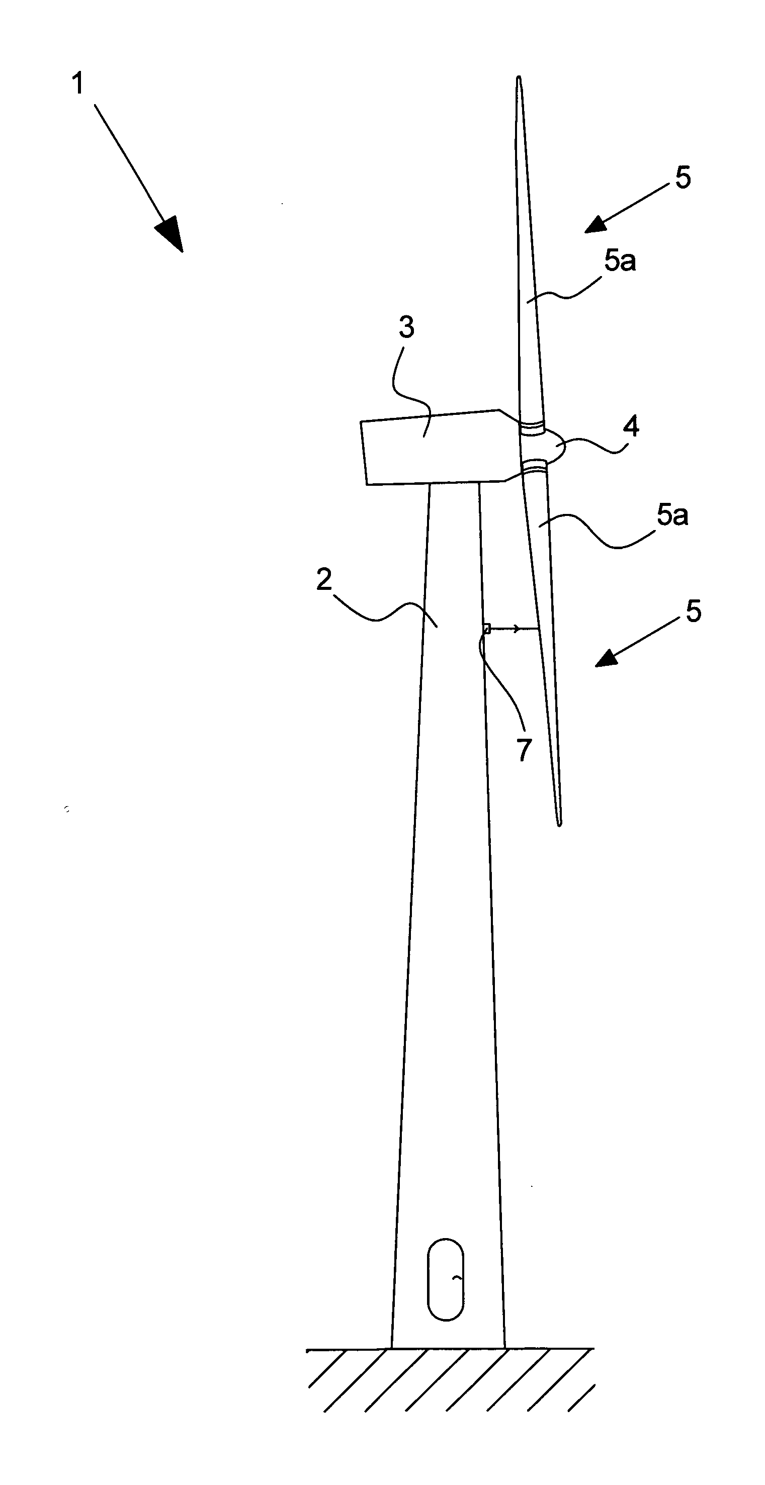
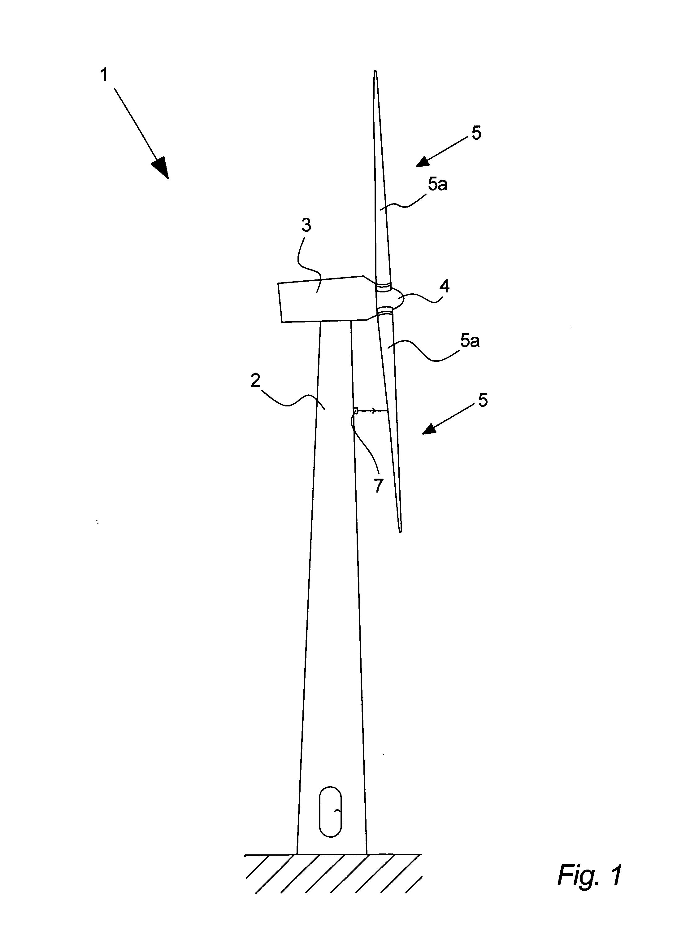
[0164]FIG. 1 illustrates one example of a side view of a structure being a modern wind turbine 1 with a tower 2, a wind turbine nacelle 3 positioned on top of the tower 2 and a rotor hub 4. The wind turbine 1 comprises a wind turbine rotor comprising at least one airfoil 5 being a wind turbine blade 5a, preferably two or three wind turbine blades 5a of well known types, such as ones made of a resin reinforced with fibreglass, carbon fibre, a metal, a composition of different materials or the like, each blade being connected to the hub 4, e.g. through a pitch mechanism (not shown) that allows the blade 5a to be turned about a longitudinal axis. A device 7 for detection of surface conditions such as formations of ice is in this embodiment of the invention arranged at the tower 2 of the wind turbine 1. It is understood that the device for detecting surface conditions 7 could also be referred to as “surface condition detecting device 7”, “device 7 for detecting surface conditions” or ju...


PUM

PropertyMeasurementUnit
wavelength rangeaaaaaaaaaa
lengthaaaaaaaaaa

Abstract

A structure including at least one airfoil, at least one device for detecting surface conditions on a surface of the at least one airfoil, and at least one sensor device, the sensor device including at least one radiation emitter adapted to emit radiation directed towards at least one surface of the airfoil, at least one first detector arranged for receiving a portion of the emitted radiation when reflected from the at least one surface and producing a first output according to an intensity thereof, at least one second detector arranged for receiving a portion of the emitted radiation when reflected from the at least one surface and producing a second output according to an intensity thereof, and control means adapted to receive and evaluate the output from the detectors based on an amount of diffuse reflected and mirror reflected radiation reflected from the at least one surface, and producing an output according thereto.

Description

TECHNICAL FIELD[0001]The present invention relates to a structure comprising a device for detection of surface conditions of airfoil(s) of the structure, a method of detecting surface conditions on airfoils of a structure, a wind park and a surface property detecting device.BRIEF DESCRIPTION OF RELATED ART[0002]Surface conditions such as ice formation on the surface of airfoils such as e.g. wind turbine blades is a well known issue to owners and manufactures of wind turbines, and can cause serious problems to the wind turbine, the wind turbine blades and the surroundings of the wind turbine. When ice is formed on a wind turbine, in particular on the blades, e.g. during standstill of the wind turbine, the turbine can be subjected to serious unintended loads which can cause overload and stress to the wind turbine blades and even to the whole wind turbine and its drive train. The formation of ice may require that the wind turbine is halted and that the operation of the wind turbine can...

Claims


Application Information

Patent Timeline
Patent Type & Authority Applications(United States)
IPC IPC(8): F03D9/00G01J4/00G01N21/55
CPCF03D11/0091F05B2270/804Y02E10/722F03D11/0025F03D7/02F03D7/06B64D15/20F03D17/00F03D80/40Y02E10/72Y02E10/74
Inventor FRIDTHJOF, JACK
Owner LIWAS
Why Eureka
Try Eureka